Horizontal well automatic anchor release hydraulic righting device

A horizontal well and hydraulic technology, applied in the direction of drilling equipment, wellbore/well components, production fluid, etc., can solve the problems of large shrinkage diameter, unsuitable casing deformation, scaling, etc., to achieve convenient withdrawal and reduce accidents The effect of card risk

Pending Publication Date: 2019-09-20
PETROCHINA CO LTD
View PDF0 Cites 1 Cited by
  • Summary
  • Abstract
  • Description
  • Claims
  • Application Information

AI Technical Summary

Problems solved by technology

The disadvantage of this kind of tool is that the spring or leaf spring directly contacts the inner wall of the casing, and the minimum shrinkage diameter is relatively large, usually 118-120mm. pipe wall of flat well

Method used


Image

  • Horizontal well automatic anchor release hydraulic righting device

Examples


Embodiment 1

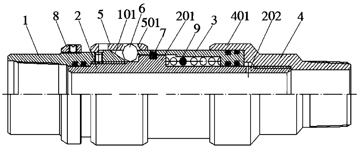
[0024] reference figure 1 The self-unlocking hydraulic centralizing device for horizontal wells of the present invention includes a front joint 1, a central tube 2, a piston tube 3, a rear joint 4, and a centralizing sleeve 5. The rear end of the front joint 1 is provided with a ring cone 101; The front end is connected with the inner side of the rear end of the front joint 1 through an external thread. A shoulder 201 is provided in the middle of the center tube 2; the piston tube 3 is slidingly sleeved on the center tube 2, and the rear end of the piston tube 2 is a necked end. Both the inner and outer side walls of the end are provided with a sealing groove, and an O-ring is fitted in the sealing groove. The front end of the piston tube 2 is slidingly fitted with the shaft shoulder 201, and the rear end is slidingly fitted with the wall of the central tube 2, and the rear of the piston tube 3 A spring 9 is arranged between the inner ring surface of the end and the shaft shoul...

Embodiment 2

[0027] On the basis of Example 1, refer to figure 1 A start pin 7 is provided between the front end of the piston tube 3 and the shaft shoulder 201. The start pin 7 can fix the piston tube 3 so that it can withstand a high pressure of 4MPa. When the pipe string is lowered to the designed position, the piston tube 3 will not be easily moved forward by the joint 1 due to external force, causing the device to be stuck in the casing. After the pipe string is set, high-pressure water is introduced into the pipe string to make the internal high pressure of the central pipe 2 exceed 4MPa, the high-pressure water pushes the piston pipe 3 to the front end, and the piston pipe 3 cuts off the start pin 7 and continues to the forward joint 1. Movement, at this time, the ball 6 protrudes from the through hole 501 on the centralizing sleeve 6 to realize the centralization of the pipe string.

Embodiment 3

[0029] On the basis of Example 1, refer to figure 1 , The front joint 1 is threadedly connected with a parallel cap 8, and a pin is connected between the cap 8 and the front joint 1. The piston tube 3 moves forward to the joint 1 under the pressure inside the center tube 2, and the roller 6 rolls in the direction of the forward joint 1 along the tapered surface 101 of the front joint 1, and at the same time, drives the centralizing sleeve 5 to the forward joint through the through hole 501 1 movement, the cap 8 fixed on the front joint 1 by a pin can limit the position of the centralizing sleeve 5.


PUM


Abstract

The invention discloses a horizontal well automatic anchor release hydraulic righting device, which comprises a front joint, a center pipe, a piston pipe, a rear joint and a righting sleeve. The front end of the righting sleeve slidably sleeves the rear end of the upper joint, and the rear end of the righting sleeve slidably sleeves the front end of the piston pipe; a plurality of through holes are formed in the surface of the righting sleeve, and a plurality balls are assembled between the inner side of the righting sleeve and the center pipe; and the diameter of the balls is larger than the aperture of the through holes, and the ball surface of each ball can stretch out from the corresponding through hole. The horizontal well automatic anchor release hydraulic righting device can keep the small diameter under the normal state, supporting righting is conducted only during setting of a string, passive righting is achieved, during pulling of the string, automatic anchor release recovery can be conducted when the internal high pressure disappears or the external pressure is high, and the jamming risk of the string can further be reduced while it is ensured that the down-hole string is centered.

Description

Technical field [0001] The invention belongs to the technical field of oilfield stratified water injection development, and in particular relates to a horizontal well self-unlocking hydraulic centralizing device. Background technique [0002] With the continuous development of horizontal well water injection development in oilfields, staged water injection of horizontal wells has become a trend. Due to the particularity of the horizontal wellbore trajectory, the downhole tools cannot be centered in the horizontal section, resulting in the inability of the water injection packer to seal, thus failing to achieve segmented water injection. Therefore, how to ensure that the downhole tools are centered in the horizontal section is the main problem faced by the staged water injection of horizontal wells. At present, the commonly used pipe string centralizing tool is the tubing centralizer. The centralizing mechanism usually uses springs or leaf springs to force the centralizing block ...

Claims


Application Information

Patent Timeline
Patent Type & Authority Applications(China)
IPC IPC(8): E21B17/10E21B43/20
CPCE21B17/1078E21B43/20
Inventor 王薇王守虎王俊涛何汝贤魏向军申晓莉蔺明阳王晓娥
Owner PETROCHINA CO LTD
Why Eureka
Try Eureka