Automatic packaging machine for optical filter switcher

A switcher and optical filter technology, applied in packaging and other directions, can solve the problems of reducing work efficiency and achieve the effect of improving work efficiency and saving manpower

Inactive Publication Date: 2022-07-29
赣州市奥海纳光电有限公司
View PDF1 Cites 0 Cited by
  • Summary
  • Abstract
  • Description
  • Claims
  • Application Information

AI Technical Summary

Problems solved by technology

[0004] We have designed an automatic packaging machine for optical filter switches with high packaging efficiency, in order to overcome the need for people to place one by one in the existing automatic packaging machine and reduce the work efficiency

Method used


Image

  • Automatic packaging machine for optical filter switcher
  • Automatic packaging machine for optical filter switcher
  • Automatic packaging machine for optical filter switcher

Examples


Embodiment 1

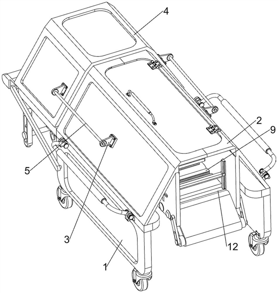
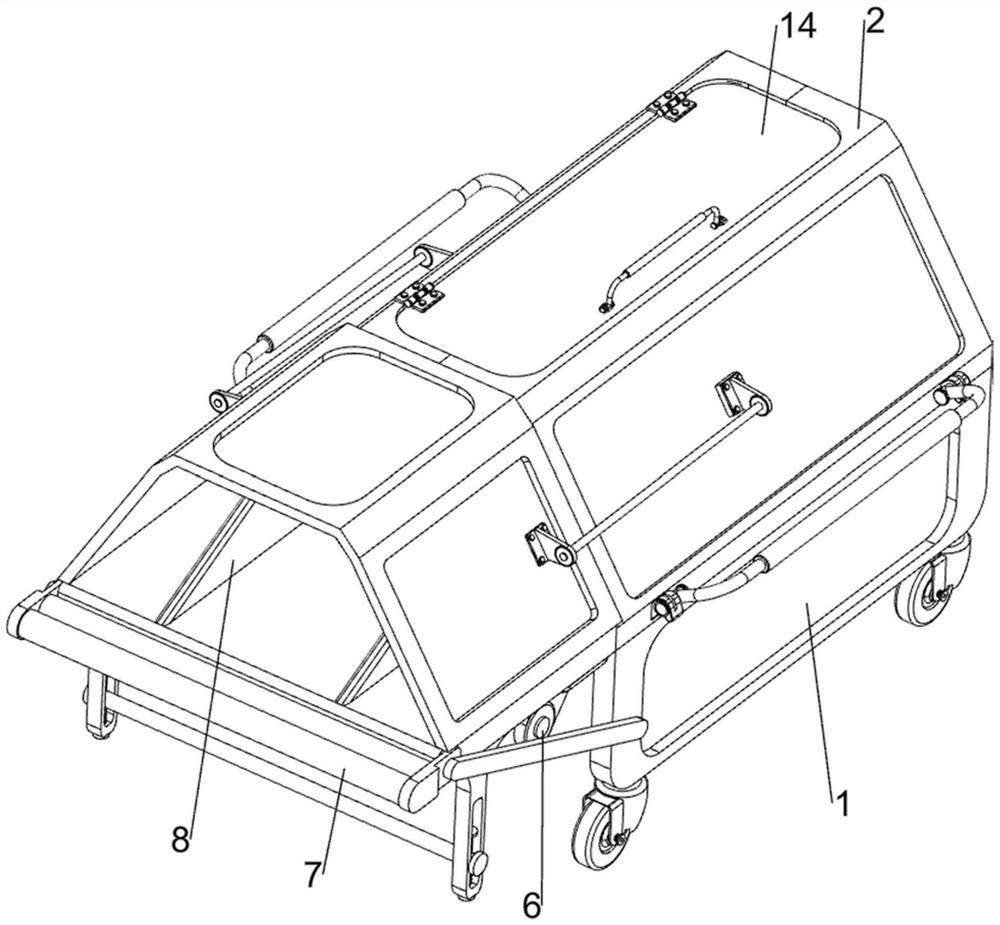
[0084] An automatic packaging machine for filter switchers, now refer to Figure 1-4 , including a support frame 1, a first protective frame 2, a limiter 3, a second protective frame 4, a first limit shaft 5, a coiler 6, a roller frame 7, a molding roller frame 71, and a winding block 8 , the tail packaging mechanism 9 and the welt packaging mechanism 10, the upper front side of the supporting frame 1 is connected with a first protective frame 2, the left and right sides of the first protective frame 2 are fixed with the stopper 3 by bolts, and the front side of the lower part of the supporting frame 1 is connected. The coiler 6 is fastened by bolts, the first limit shaft 5 is slidably connected to the two limiters 3, and the second protective frame 4 is connected between the rear sides of the two first limit shafts 5. The second protective frame 4 is slidably connected with the first protective frame 2 and the supporting frame 1. Two winding blocks 8 are fixedly connected to ...

Embodiment 2

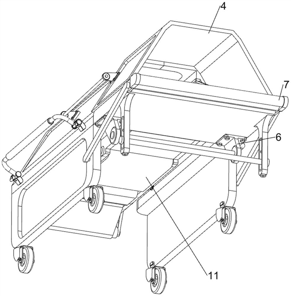
[0089] On the basis of Example 1, now refer to image 3 , Figure 4 , Figure 7 , Figure 8 and Figure 10 , also includes a push mechanism 11, the push mechanism 11 includes a third gear 111, a fourth gear 112, a connecting rod 113, a third shaft 114, a fourth shaft 115, a fifth gear 116, a conveying belt 117 and a transmission belt 118, A third gear 111 is connected to the left side of the first rotating shaft 108 , a fourth gear 112 is rotatably connected to the left front side of the first protective frame 2 , the fourth gear 112 meshes with the third gear 111 , and the fourth gear 112 drives the shaft The left side is rotatably connected with the connecting rod 113, the first protective frame 2 is rotatably connected with three third rotating shafts 114, the first protective frame 2 is rotatably connected with three fourth rotating shafts 115, and the first third rotating shaft 115 on the front side is rotatably connected. A conveying belt 117 is wound around the rota...


PUM


Abstract

The invention relates to an automatic packaging machine, in particular to an automatic packaging machine for an optical filter switcher. The invention provides the automatic packaging machine for the optical filter switcher, which is high in packaging efficiency. An automatic packaging machine for an optical filter switcher comprises a supporting frame, a first protection frame, a limiting stopper, a second protection frame, a first limiting shaft and the like. A first protection frame is connected to the front side of the upper portion of the supporting frame, limiters are connected to the left side and the right side of the first protection frame, first limiting shafts are slidably connected to the two limiters, a second protection frame is connected between the rear sides of the two first limiting shafts, and the second protection frame is slidably connected with the first protection frame and the supporting frame. A plurality of optical filter switchers are placed in a folded plastic film by people, then the rotating welt packaging device drives the plastic film to move forwards, and the air cylinder is started to enable the first packaging device to move downwards to package the plastic film, so that the automatic packaging effect is achieved, and the working efficiency of people is improved.

Description

technical field [0001] The invention relates to an automatic packaging machine, in particular to an automatic packaging machine for a filter switcher. Background technique [0002] After the filter switcher is produced, in order to prevent the filter switcher from being damaged during transportation, people will package the filter switcher. Therefore, a packaging machine needs to be designed. [0003] Patent application: CN113659250A, published on 20211116, discloses an automatic packaging machine, which includes a heat-sealing mechanism, a cell transfer module and two material-carrying fixtures. The heat-sealing mechanism includes a bracket and two hot-pressed parts, two The hot pressing parts are respectively arranged on the opposite sides of the bracket, and a heat sealing area is arranged between the two hot pressing parts; Each is provided with a swing arm, and the rotating drive part is used to drive the two swing arms to enter the heat sealing area alternately; the t...

Claims


Application Information

Patent Timeline
Patent Type & Authority Applications(China)
IPC IPC(8): B65B35/44B65B43/02B65B61/06
CPCB65B35/44B65B43/02B65B61/06
Inventor 高群张学智高睿肖莘耀翁海滨朱静
Owner 赣州市奥海纳光电有限公司
Why Eureka
Try Eureka