
Moving mechanism and intelligent classification garbage kiosk based on same
A mobile mechanism and garbage kiosk technology, which is applied in the direction of garbage cans, garbage collection, household appliances, etc., can solve the problems of inconvenient garbage kiosks to stop at a certain position, complicated operation, etc., and achieve difficult position movement, simple operation, and reasonable structure Effect
- Summary
- Abstract
- Description
- Claims
- Application Information
AI Technical Summary
Problems solved by technology
Method used
Image

Examples
Embodiment 1
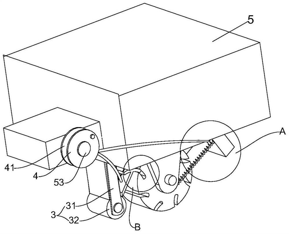
[0052] Example 1, please refer to the attached manual Figure 2-4 , the present invention provides a technical solution: a moving mechanism, including:
[0053] Wheel 1: used to drive the moving mechanism to move, the wheel 1 is covered with a wheel frame 11, the wheel 1 is provided with a plurality of locking holes 12 arranged in a circular array, and the wheel frame 11 can be fixed on the base 5 superior;
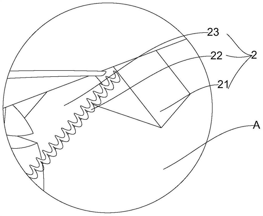
[0054] Brake mechanism 2: used for the runner 1 during deceleration operation, including a swash plate 21 hinged on one side of the runner frame 11, and a restoring spring 22 is provided between the swash plate 21 and the runner frame 11, preferably, in this embodiment The number of the restoring springs 22 is two, and the brake pad 23 is fixedly connected to the side of the inclined plate 21 facing the runner 1. Preferably, the brake pad 23 is cylindrical;
[0055] Locking mechanism 3: used to lock the stationary runner 1, including two clamping plates 31 arranged on t...
Embodiment 2
[0060] Example 2, please refer to the attached manual Figure 5 and the instruction manual Image 6 , On the basis of the structure of Embodiment 1, this embodiment improves the locking mechanism 3, and the locking mechanism 3 can also be provided with a locking block composed of a connecting rod 33 and an arc-shaped block 34 on both sides of the circular block 32, In this embodiment, the number of the runners 1 is two, and they are distributed on both sides of the circular block 32. In normal state, under the action of gravity, the two arc-shaped blocks 34 are snapped into the corresponding locking holes 12 and locked. The runner 1 is locked, so that the locking action of the two runners 1 is realized through a set of locking mechanisms 3, and the practical application effect is stronger.
Embodiment 3
[0061] Example 3, please refer to the attached manual Figure 7-9 and the instruction manual Figure 13 , Based on Embodiment 1 or Embodiment 2, this embodiment improves the runner frame 11 and the runner 1, and installs a screw 111 and a driving motor 112 on the runner frame 11. The driving motor 112 is the power source, and the driving screw 111 rotates , the base 5 is provided with a threaded groove 51, which is threaded with the screw 111. During the rotation of the screw 111, the base 5 moves in the vertical direction. The locking hole 12 of the runner 1 is provided with a drive switch 121. The drive switch 121 and the The drive motor 112 is electrically connected to control the opening and closing of the drive motor 112. In actual use, after the arc block 34 penetrates into the locking hole 12, the arc block 34 contacts the drive switch 121, so that the drive motor 112 runs and drives the The screw 111 is rotated forward, so that the base 5 moves downward in the vertica...
PUM
 Abstract
Description
Claims
Application Information