Highway construction quality supervision equipment and method
A construction quality, highway technology, applied in chemical instruments and methods, roads, roads, etc., can solve problems such as residual sand blocking, road unevenness, affecting road quality, etc., and achieve a high degree of automation.
Pending Publication Date: 2022-07-29
湖北省高创公路工程咨询监理有限公司
4 Cites 0 Cited by
AI-Extracted Technical Summary
Problems solved by technology
[0004] When the quality of the concrete poured on the road is insufficient, it is easy to cause a large amount of residual sand on the surface of the final paved road. Traditional staff judge the ...
Abstract
The invention relates to the technical field of highway construction monitoring, in particular to highway construction quality supervision equipment and method.The highway construction quality supervision equipment comprises a machine box, a push handle, a plurality of universal wheels and a controller, the push handle and the controller are both arranged on the machine box, the universal wheels are symmetrically arranged on the machine box, and the supervision equipment comprises a sand suction cover, a sand suction pipe and a sand suction pipe; the motor is movably arranged on the case; the telescopic element is arranged on the case, and the output end of the telescopic element is connected with the sand suction cover; the supervision system is arranged in the case, communicates with the sand suction cover and is used for detecting the content of residual sand on the surface of the construction ground and collecting the residual sand; the recovery system is arranged in the case and is connected with the supervision system; the whole device is high in automation degree, the amount of residual sand in a unit area on the surface of a construction road can be automatically detected and converted into data, and therefore workers can more accurately judge the quality condition of the construction road surface conveniently, and the traditional mode that the workers recognize and judge with naked eyes is omitted.
Application Domain
Road cleaningMaterial testing goods +3
Technology Topic
Structural engineeringAutomation +3
Image
Examples
- Experimental program(1)
Example Embodiment
[0060] The technical solutions in the embodiments of the present invention will be clearly and completely described below with reference to the accompanying drawings in the embodiments of the present invention. Obviously, the described embodiments are only a part of the embodiments of the present invention, but not all of the embodiments. Based on the embodiments of the present invention, all other embodiments obtained by those of ordinary skill in the art without creative work fall within the protection scope of the present invention. The present invention will be further described below with reference to the embodiments.
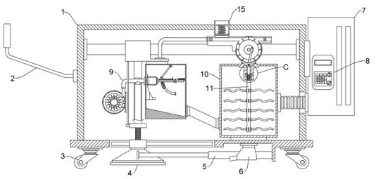
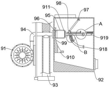
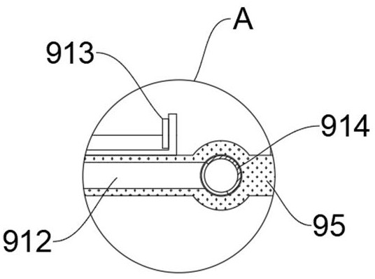
[0061] see Figure 1-Figure 8 , in one embodiment of the present application, a kind of highway construction quality supervision equipment and method, including a chassis 1, a push handle 2, several universal wheels 3 and a controller 8, the push handle 2 and the controller 8 are set On the chassis 1, several universal wheels 3 are symmetrically arranged on the chassis 1, and the supervision equipment includes:
[0062] The sand suction hood 4 is movably arranged on the chassis 1;
[0063] The telescopic element is arranged on the chassis 1 and its output end is connected to the sand suction hood 4;
[0064] A supervision system 9, arranged in the cabinet 1 and communicated with the sand suction hood 4, is used to detect and collect the residual sand content on the surface of the construction ground; and
[0065] The recycling system is arranged in the cabinet 1 and connected to the supervision system 9. The recycling system can process the residual sand collected by the supervision system 9 into mortar and lay it on the construction ground; wherein
[0066] The supervision system 9 includes:
[0067] The air extraction pipe 93 is arranged on the chassis 1 and one end is communicated with the sand suction cover 4 through the organ pipe;
[0068] The sandbox 92 is arranged in the chassis 1 and communicated with the recycling system;
[0069] The blower 91 is arranged in the case 1, the output end of the blower 91 is provided with an output pipe 94 that penetrates the air extraction pipe 93, one end of the output pipe 94 is communicated with the sand collecting box 92, and the output pipe 94 is provided with a sand mouth communicated with the air extraction pipe 93 ;as well as
[0070] The supervision module is arranged in the collection sandbox 92 and is used for monitoring the amount of residual sand entering the collection sandbox 92. The supervision module is connected with the recycling system, and can control the recycling system to work synchronously when the supervision module works.
[0071] It should be noted that the telescopic element can be a linear motor, a cylinder or a hydraulic cylinder. In this embodiment, the telescopic element is preferably an electric telescopic rod 5, and the electric telescopic rod 5 is arranged on the chassis 1 and the sand suction Between the covers 4, the specific model of the electric telescopic rod 5 is not specifically limited here.
[0072] In a specific case of this embodiment, the supervision module includes:
[0073] The monitoring seat 95, the middle position of the monitoring seat 95 is rotatably installed in the sand box 92 through a hollow rotating shaft 914, the rotating shaft 914 is provided with a gap, and the monitoring seat 95 is formed with a channel 912 that communicates with the gap, and the channel 912 There is a gauze 911 inside;
[0074] The arc-shaped slope 99 is arranged in the sand collecting box 92, the arc-shaped slope 99 and the monitoring base 95 are slidably matched, and the arc-shaped slope 99 is provided with a discharge port 910;
[0075] The sliding block 98 is movably arranged on the monitoring base 95, the sliding block 98 is movably connected to the sand box 92 through the driving rod 97, and the opposite surfaces of the sliding block 98 and the monitoring base 95 are provided with electromagnets 913 that are energized and repel each other. ;
[0076] a limiting unit, arranged between the sandbox 92 and the monitoring seat 95, for limiting the position of the monitoring seat 95; and
[0077] The transmission unit is arranged in the sand collecting box 92 and is connected with the monitoring base 95, and the operation of the recovery system can be controlled by the transmission unit when the monitoring base 95 moves.
[0078] It should be added that a compensation frame 96 is movably inserted at one end of the monitoring base 95 , the compensation frame 96 is slidably fitted with the arc slope 99 , and the compensation frame 96 is elastically connected to the monitoring base 95 .
[0079] In practical application, the entire supervision equipment is moved to the completed road and the fan 91 is started to work through control. When the fan 91 is working, a high-speed flow of air can be input into the output pipe 94, thereby generating negative pressure at the sand mouth, and the road The residual sand on the construction surface is discharged into the channel 912 in the monitoring base 95 along the sand suction hood 4, the air suction pipe 93 and the output pipe 94 for storage; at the same time, the electric telescopic rod 5 is controlled to work to adjust the position of the sand suction hood 4, and the gas can The chassis 1 is discharged along the channel 912 and the rotating shaft 914. When the amount of residual sand in the monitoring seat 95 reaches the set threshold, the limit unit fails at this time, and the fan 91 and the electric telescopic rod 5 stop working, and the monitoring seat 95 rotates until the channel 912 is communicated with the discharge port 910, and the residual sand is discharged from the monitoring seat 95. At this time, the transmission unit can be used to feed back to the controller 8. The controller 8 records the number of rotations of the monitoring seat 95 and converts it into residual sand content data. The controller 8 controls The electromagnet 913 is energized and repelled, so that the monitoring base 95 is reset for the next sand residue collection work. The whole device has a high degree of automation, and can automatically detect and convert the residual sand amount in the unit area of the construction road surface into data, which is convenient for The staff can more accurately judge the quality of road construction pavement.
[0080] see figure 1 , figure 2 , Figure 4 , Figure 5 as well as Image 6 , as another preferred embodiment of the present application, the limiting unit includes a trapezoidal portion 919, a hinge plate 920 and a set of movable plates 921;
[0081] The trapezoidal portion 919 is arranged at one end of the monitoring base 95, one end of the hinge plate 920 is hinged in the sand box 92, and a torsion spring is provided at the hinge, and a window for the trapezoid portion 919 to pass through is formed on the hinge plate 920. The set of movable plates 921 is symmetrical and movably arranged in the window, the movable plates 921 and the hinge plates 920 are elastically connected, and there is a gap between adjacent movable plates 921 whose size matches the small end of the trapezoidal portion 919 .
[0082] Exemplarily in this embodiment, the transmission unit includes an inflation tube 915, a No. 1 piston 917, a sensing element, and a counteracting head 918;
[0083] The inflatable tube 915 is arranged on the monitoring base 95 , the No. 1 piston 917 is movably arranged in the inflatable tube 915 and the two are elastically connected, the sensing element is arranged on the No. 1 piston 917 , and the interference head 918 is arranged in the sand box 92 . , the sensing element is located on the moving path of the No. 1 piston 917 and is electrically connected to the electromagnet 913, and the No. 1 piston 917 is also connected to the recovery system.
[0084] It should be noted that the sensing element may be an infrared ranging sensor or a laser ranging sensor. In this embodiment, the sensing element is preferably a pressure sensor 922, and the pressure sensor 922 is provided on the No. 1 piston 917 and on the moving path of the interference head 918 .
[0085] As the amount of residual sand in the channel 912 increases until the residual sand content reaches the set threshold, the gravity of the residual sand on the monitoring base 95 is greater than the torsion force of the torsion spring at the hinged position of the hinge plate 920, so that the hinged plate 920 can move along its hinged position. At this time, the monitoring seat 95 rotates along the rotating shaft 914, the interference head 918 is inserted into the inflatable tube 915, and drives the No. 1 piston 917 to move. The movement of the No. 1 piston 917 can control the synchronous operation of the recovery system. During the extrusion operation, the pressure sensor 922 feeds back the rotation signal of the monitoring seat 95 to the controller 8, and the controller 8 can record the rotation times of the monitoring seat 95 and convert it into the residual sand content, and after a period of time, can control the electromagnet 913 to energize Repel each other, so that the monitoring seat 95 that discharges the residual sand is reset. At this time, the small end of the trapezoidal portion 919 can cooperate with the movable plate 921, so as to reset smoothly and complete the detection of the residual sand.
[0086] see figure 1 , figure 2 , Figure 4 , Figure 7 as well as Figure 8 , as another preferred embodiment of the present application, the recovery system includes:
[0087] The feeding box 7 is arranged on the chassis 1;
[0088] The mixing box 10 is arranged in the casing 1 and communicates with the feeding box 7 and the sand collecting box 92. The casing 1 is provided with a discharge nozzle 6 that communicates with the mixing box 10;
[0089] The stirring roller 11 is movably arranged in the mixing box 10;
[0090] The drive shaft 12 is movably arranged in the mixing box 10, a steering unit is provided between the drive shaft 12 and the stirring roller 11, and the rotation of the stirring roller 11 can be controlled by the steering unit when the driving shaft 12 moves; and
[0091] The driving module 15 is arranged between the driving shaft 12 and the No. 1 piston 917 , and the position of the driving shaft 12 relative to the stirring roller 11 can be adjusted through the driving module 15 when the No. 1 piston 917 moves.
[0092] Exemplarily in this embodiment, the driving module 15 includes:
[0093] The drive box 151 is arranged in the chassis 1, and the drive box 151 is provided with an exhaust flow channel 158, and one end of the exhaust flow channel 158 communicates with the exhaust hole 916 formed in the inflation pipe 915;
[0094] The one-way valve 155 is arranged at one end of the exhaust flow channel 158;
[0095] The electric valve 157 is arranged at the other end of the exhaust flow channel 158;
[0096] The No. 2 piston 156 is movably arranged in a reserved cavity in the exhaust flow channel 158, and the No. 2 piston 156 is elastically connected with the drive box 151; and
[0097] The execution unit is disposed in the exhaust flow channel 158 and connected to the drive shaft 12, and the execution unit can be controlled to work when the gas passes through the execution unit.
[0098] It should be noted that the drive module 15 in this embodiment is not limited to the above-mentioned mechanical replacement structure, and can also be replaced by a linear motor or an air cylinder to control the movement of the drive shaft 12 , which is not specifically limited here.
[0099] In practical application, the residual sand in the sand collecting box 92 is discharged into the mixing box 10, and each time the interference head 918 and the No. 1 piston 917 collide, the No. 1 piston 917 is driven to move along the inflation tube 915, thereby inflating the air The air in the pipe 915 is squeezed into the exhaust runner 158, so that the No. 2 piston 156 follows the reserved cavity such as Figure 7Move up in the direction shown, so as to store the air. When the detection of the residual sand content of the construction road is completed, the controller 8 can control the feeding box 7 to add the corresponding amount to the mixing box 10 according to the measured residual sand amount. The rest of the mortar raw materials in the volume, the staff controls the electric valve 157 to open, and the air in the reserved cavity is discharged along the exhaust flow channel 158 to drive the execution unit to work, and the execution unit can drive the drive shaft 12 to reciprocate in the vertical direction. Under the action of the steering unit, it can drive the stirring roller 11 to rotate repeatedly to realize the preparation of the mortar, and at the same time control the opening of the discharge nozzle 6 to move the whole device, realize the laying of the mortar, and realize the recycling of the residual sand. .
[0100] see figure 1 , figure 2 , Figure 4 , Figure 7 as well as Figure 8 , as another preferred embodiment of the present application, the execution unit includes a drive disk 152, a turntable 154 and a push rod 153;
[0101] The drive disk 152 and the turntable 154 are coaxially connected and movably arranged together in the exhaust flow channel 158 . The outer wall of the drive disk 152 is surrounded by a number of contact blades, and the push rod 153 is movably connected to the eccentric of the drive disk 152 . between the position and the drive shaft 12 .
[0102] Exemplarily in this embodiment, the steering unit includes at least one ball 13 and a helical groove 14, the ball 13 is slidably embedded in one end of the drive shaft 12, and one end of the drive shaft 12 is inserted in the stirring roller 11, A helical groove 14 is formed in the stirring roller 11 , and the helical groove 14 and the ball 13 are slidably matched.
[0103] In practical application, the gas collides with the conflicting blades through the exhaust flow channel 158, and drives the drive disc 152 and the turntable 154 to rotate together, thereby driving the drive shaft 12 to reciprocate under the action of the drive rod 97. Under the sliding cooperation between 13, the stirring roller 11 is driven to rotate continuously, so that the preparation of mortar can be realized.
[0104] A supervision method for expressway construction quality supervision equipment, comprising the following steps:
[0105] S100: Move the entire supervision equipment to the road where the construction has been completed and start the fan 91 through control to work, and discharge the residual sand existing on the road construction surface into the monitoring seat 95 along the sand suction cover 4, the air suction pipe 93 and the output pipe 94. Stored in channel 912;
[0106] S200: When the content of the residual sand stored in the channel 912 reaches the set threshold and the gravity is greater than the torsion force of the torsion spring at the hinged part of the hinge plate 920, the limiting unit fails, and the monitoring base 95 rotates along its rotating installation position and smoothes the residual sand. The discharge port 910 is discharged into the sand collecting box 92, and finally flows into the mixing box 10;
[0107] S300 : every time the monitoring seat 95 rotates, the contact head 918 can meet the sensing element, so that the sensing element records the number of rotations of the monitoring seat 95 , and finally the controller 8 converts the number of rotations of the monitoring seat 95 into the amount of residual sand .
[0108] S400: The controller 8 compares the recorded residual sand amount with its internally recorded benchmark data to judge the quality of the road construction surface.
[0109] How this application works:
[0110] Move the entire supervision equipment to the completed highway and start the fan 91 through control. When the fan 91 is working, a high-speed airflow can be input into the output pipe 94, thereby generating a negative pressure at the sand mouth and removing the residual existing on the road construction surface. The sand is discharged into the channel 912 in the monitoring seat 95 along the sand suction hood 4, the suction pipe 93 and the output pipe 94 for storage; at the same time, the electric telescopic rod 5 is controlled to work to adjust the position of the sand suction hood 4, and the gas can follow the channel 912 and The rotating shaft 914 is discharged from the chassis 1. With the increase of the amount of residual sand in the channel 912 until the residual sand content reaches the set threshold, the gravity of the residual sand to the monitoring base 95 is greater than the torsion force of the torsion spring at the hinge plate 920, so that the hinge plate 920 is hinged. The plate 920 rotates along its hinge joint, at this time the monitoring seat 95 rotates along the rotating shaft 914, the interference head 918 is inserted into the inflatable tube 915, and drives the No. 1 piston 917 to move. 922 is squeezed by the conflicting head 918, and the pressure sensor 922 feeds back the rotation signal of the monitoring seat 95 to the controller 8. The controller 8 can record the number of rotations of the monitoring seat 95 and convert it into residual sand content, and after a period of time, The electromagnet 913 can be controlled to be energized and repelled, so that the monitoring seat 95 that discharges the residual sand can be reset. At this time, the small end of the trapezoidal part 919 can be matched with the movable plate 921, so as to reset smoothly and complete the detection of the residual sand;
[0111] The residual sand in the sand collecting box 92 is discharged into the mixing box 10, and each time the collision head 918 collides with the No. 1 piston 917, the No. 1 piston 917 is driven to move along the inflating tube 915, so as to displace the air in the inflating tube 915. Squeeze into the exhaust runner 158 so that the No. 2 piston 156 follows the reserved cavity such as Figure 7 Move up in the direction shown, so as to store the air. When the detection of the residual sand content of the construction road is completed, the controller 8 can control the feeding box 7 to add the corresponding amount to the mixing box 10 according to the measured residual sand amount. The rest of the mortar raw materials in the volume are controlled by the staff to open the electric valve 157, and the gas passes through the exhaust flow channel 158 to collide with the conflicting blades, and drives the drive disc 152 and the turntable 154 to rotate together, so that under the action of the drive rod 97, the drive is driven. The shaft 12 reciprocates, and under the sliding cooperation between the spiral groove 14 and the ball 13, the stirring roller 11 is driven to rotate continuously to realize the preparation of mortar, and at the same time, the discharge nozzle 6 is controlled to open, and the entire device is moved to realize the laying of mortar. work to achieve the recycling of residual sand.
[0112] The present invention and its embodiments have been described above schematically, and the description is not restrictive, and what is shown in the accompanying drawings is only one of the embodiments of the present invention, and the actual structure is not limited thereto. Therefore, if those of ordinary skill in the art are inspired by it, without departing from the purpose of the present invention, any structural modes and embodiments similar to this technical solution are designed without creativity, which shall belong to the protection scope of the present invention. .
[0113] In addition, it should be understood that although this specification is described in terms of embodiments, not each embodiment only includes an independent technical solution, and this description in the specification is only for the sake of clarity, and those skilled in the art should take the specification as a whole , the technical solutions in each embodiment can also be appropriately combined to form other implementations that can be understood by those skilled in the art.
PUM


Description & Claims & Application Information
We can also present the details of the Description, Claims and Application information to help users get a comprehensive understanding of the technical details of the patent, such as background art, summary of invention, brief description of drawings, description of embodiments, and other original content. On the other hand, users can also determine the specific scope of protection of the technology through the list of claims; as well as understand the changes in the life cycle of the technology with the presentation of the patent timeline. Login to view more.