

Anti-blocking device, garbage disposer and control method of garbage disposer
A technology of a garbage disposer and a control method, which is applied to water supply devices, indoor sanitary plumbing installations, buildings, etc., and can solve problems such as the garbage disposer is prone to clogging, and achieve the effect of solving clogging and slowing down the deposition phenomenon
- Summary
- Abstract
- Description
- Claims
- Application Information
AI Technical Summary
Problems solved by technology
Method used
Image

Examples
no. 1 example
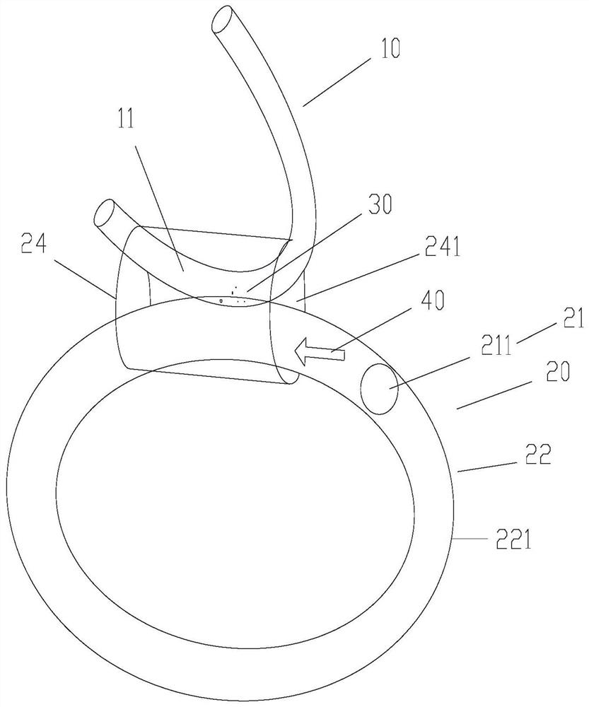
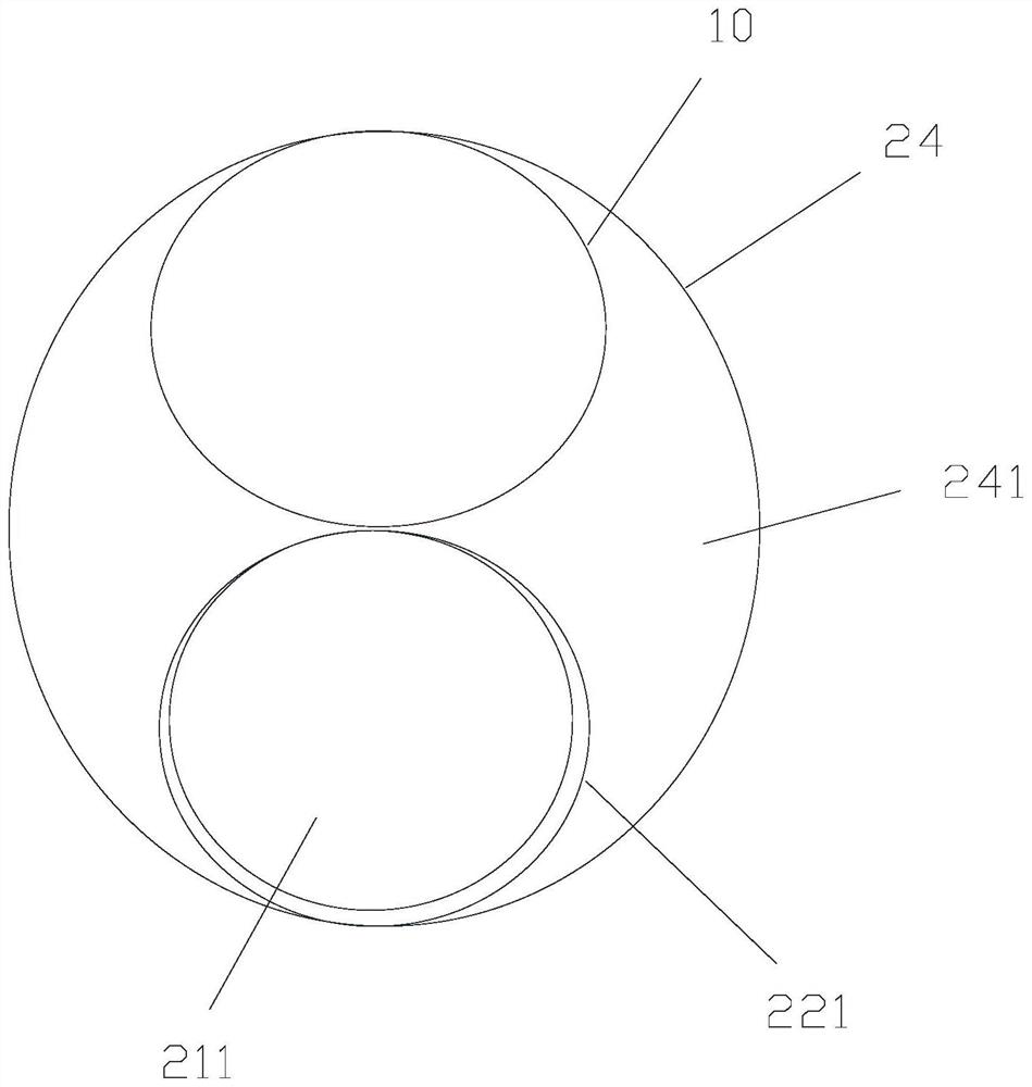
[0037] In the first embodiment, as figure 1 and figure 2 As shown, the anti-blocking assembly 20 includes: a hose 221, the hose 221 is arranged adjacent to the sewage pipe 10, the hose 221 has an abutting state for abutting with the sewage pipe 10 after being filled with fluid, and the hose 221 is used to avoid the hose 221's avoidance state. The hose 221 here refers to a soft pipe body. By introducing gas or fluid into the pipe body, the pipe body can be deformed. Connected state; when the tube body is not filled with gas or liquid, the hose 221 is in a flattened state so as to be in an avoidance state.
[0038] In the first embodiment, the anti-blocking assembly 20 further includes: a first pusher 211 , the first pusher 211 is disposed in the hose 221 to push the first pusher 211 to move under the drive of the fluid in the hose 221 , so as to push the sediment in the sewage pipe 10 through the first pushing member 211 .
[0039] In the first embodiment, the first pushin...
no. 2 example
[0050] In the second embodiment, the sewage pipe 10 has a sediment elbow section 11 for accommodating the sediment 30, and the anti-blocking assembly 20 further includes: a moving guide rail; a second pushing member, the second pushing member is relatively movably installed on the moving guide rail On the other hand, the second pushing member has a pressing state in which it is moved to abut against the sediment elbow section 11 and an avoidance state in which it is separated from the sediment elbow section 11 .
[0051] In an implementation manner, the moving guide rail here can be a rack, and the second pushing member is used as the pushing member 21 , which may include a gear meshing with the rack and the sediment elbow section 11 for pushing the sewage pipe 10 . the abutting push parts.
[0052] In another implementation manner, a slideway portion is provided on the moving guide rail here, the second pusher is used as the pusher member 21, and the second pusher is slidably...
no. 3 example
[0054] In the third embodiment, the sewage pipe 10 has a sediment elbow section 11 for accommodating the sediment 30, and the anti-blocking assembly 20 further includes a vibration part, which is installed on the sewage pipe 10 to drive the sediment elbow through the vibration part. Section 11 vibrates. In this embodiment, the sewage pipe 10 can be directly moved by the vibrating component, so as to promote the movement of the sediment in the sediment elbow section 11 .
[0055] In order to detect the sediment in the sewage pipe 10 , the anti-blocking device further includes: a detection part, which is in contact with the sewage pipe 10 to detect whether the sediment in the sewage pipe 10 reaches a state to be cleaned.
PUM
 Abstract
Description
Claims
Application Information