
Scroll compressor

A scroll compressor and compression mechanism technology, applied in the field of scroll compressors, can solve the problems of complexity, difficult structural design, and the compressor does not have a radially flexible structure and an axially flexible structure.

Pending Publication Date: 2022-07-29
EMERSON CLIMATE TECH (SUZHOU) CO LTD
View PDF0 Cites 0 Cited by
  • Summary
  • Abstract
  • Description
  • Claims
  • Application Information

AI Technical Summary

Problems solved by technology

[0005] However, for a compressor with a twin-scroll compression mechanism, due to the complex movement of the twin-scroll compression mechanism and the stress of each component, the structural design is more difficult and complicated, and the size is also larger
In particular, existing compressors with twin-scroll compression mechanisms do not have a radially flexible structure and / or an axially flexible structure, or have a very complicated axially flexible structure

Method used


Image

  • Scroll compressor
  • Scroll compressor
  • Scroll compressor

Examples


Embodiment Construction

[0045] The following descriptions of various embodiments of the present invention are exemplary only, and in no way limit the invention and its application or usage. The same reference numerals are used to denote the same components in the various drawings, and thus the configuration of the same components will not be described repeatedly.

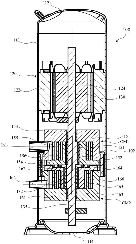
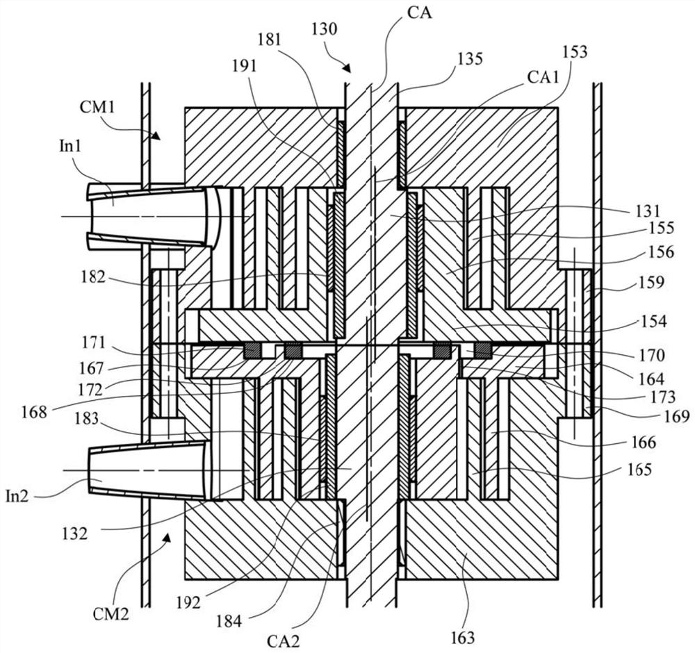
[0046] figure 1 is a schematic longitudinal section of a scroll compressor according to an embodiment of the present disclosure; figure 2 Yes figure 1 A partially enlarged schematic diagram of the compression mechanism of the scroll compressor. The following will refer to figure 1 and figure 2 The scroll compressor according to the present disclosure will be described.

[0047] like figure 1 and figure 2 As shown, the scroll compressor 100 includes a casing 110 , a top cover 112 disposed at one end of the casing 110 and a bottom cover 114 disposed at the other end of the casing 110 . Housing 110. Top cover 112 and bottom cover 1...


PUM


Abstract

The invention provides a scroll compressor. The scroll compressor comprises a first scroll compression mechanism, a second scroll compression mechanism, a driving shaft and a bushing, the first scroll compression mechanism has a first fixed scroll and a first orbiting scroll movable relative to the first fixed scroll to compress a working fluid. The second scroll compression mechanism has a second stationary scroll and a second orbiting scroll movable relative to the second stationary scroll to compress the working fluid. The drive shaft includes a first eccentric journal engaged with the first orbiting scroll to be able to drive the first orbiting scroll and a second eccentric journal engaged with the second orbiting scroll to be able to drive the second orbiting scroll. The bushing is disposed between the first orbiting scroll and the first eccentric journal and / or between the second orbiting scroll and the second eccentric journal, and is configured to allow radial separation between the first fixed scroll and the first orbiting scroll and / or between the second fixed scroll and the second orbiting scroll under certain conditions.

Description

technical field [0001] The present disclosure relates to a scroll compressor, and more particularly, to a scroll compressor with a dual compression mechanism. Background technique [0002] The content in this section merely provides background information related to the present disclosure and may not constitute prior art. [0003] The scroll compressor may include a first scroll compression mechanism and a second scroll compression mechanism to meet capacity requirements. The first scroll compression mechanism and the second scroll compression mechanism each include a fixed scroll and an orbiting scroll, wherein the orbiting scroll orbits relative to the corresponding fixed scroll to compress the working fluid. [0004] During the operation of the compressor, impurities are inevitably introduced into the compression mechanism, specifically, between the intermeshing wraps of the fixed scroll and the movable scroll. At this time, in order to avoid damage to the wraps, it is ...

Claims


Application Information

Patent Timeline
Patent Type & Authority Applications(China)
IPC IPC(8): F04C18/02F04C23/00F04C27/00F04C29/12
CPCF04C18/0215F04C23/001F04C27/00F04C29/12F04C2240/30
Inventor 黄幼玲束宏飞
Owner EMERSON CLIMATE TECH (SUZHOU) CO LTD
Learn More