
Metal fan wheel, fan and electronic product

A technology of electronic products and fan wheels, which is applied in the direction of electric digital data processing, instruments, liquid fuel engines, etc., can solve the problems of fan noise, etc., and achieve the effects of reducing noise, uniform distribution, and solving energy concentration

Pending Publication Date: 2022-07-29
昆山品岱电子有限公司
View PDF0 Cites 0 Cited by
  • Summary
  • Abstract
  • Description
  • Claims
  • Application Information

AI Technical Summary

Problems solved by technology

[0004] The purpose of the present invention is to provide a metal fan wheel, fan and electronic product to solve the problem of noise caused by the fan running in the prior art

Method used


Image

  • Metal fan wheel, fan and electronic product
  • Metal fan wheel, fan and electronic product
  • Metal fan wheel, fan and electronic product

Examples


Embodiment 1

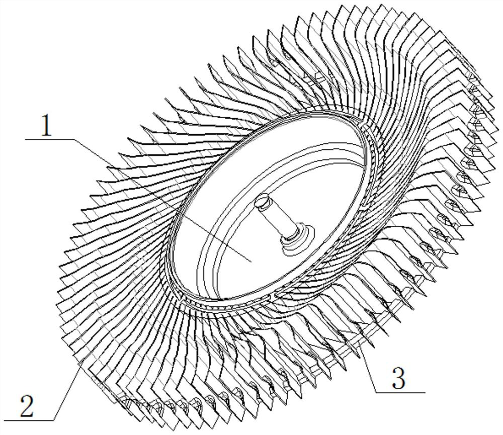
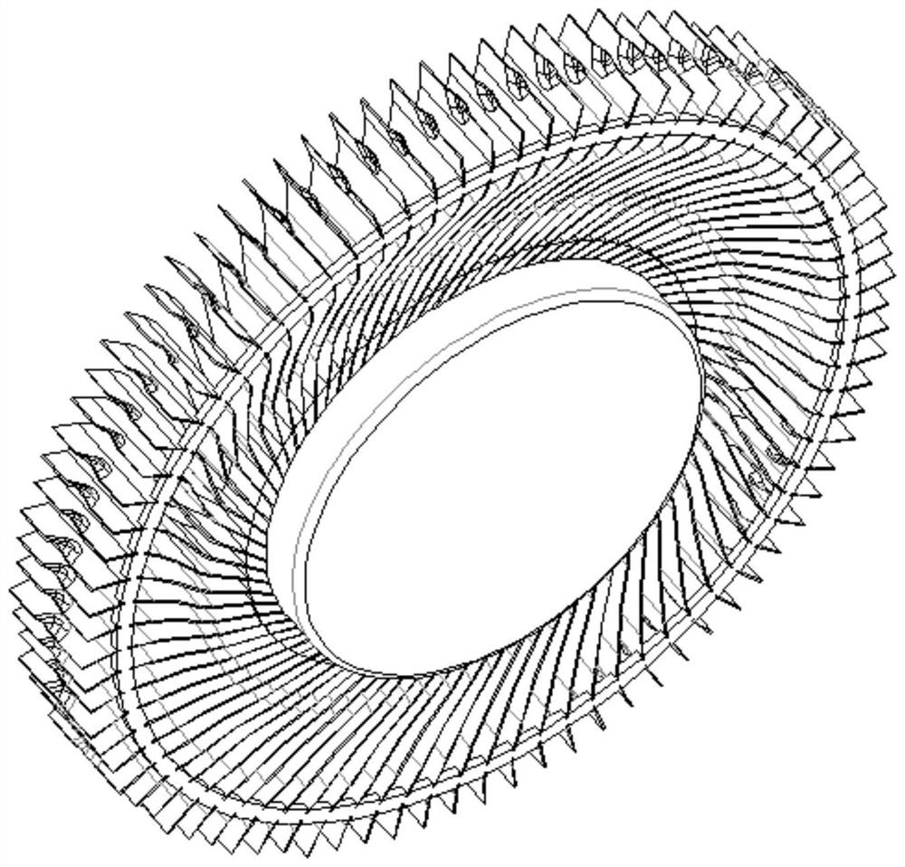
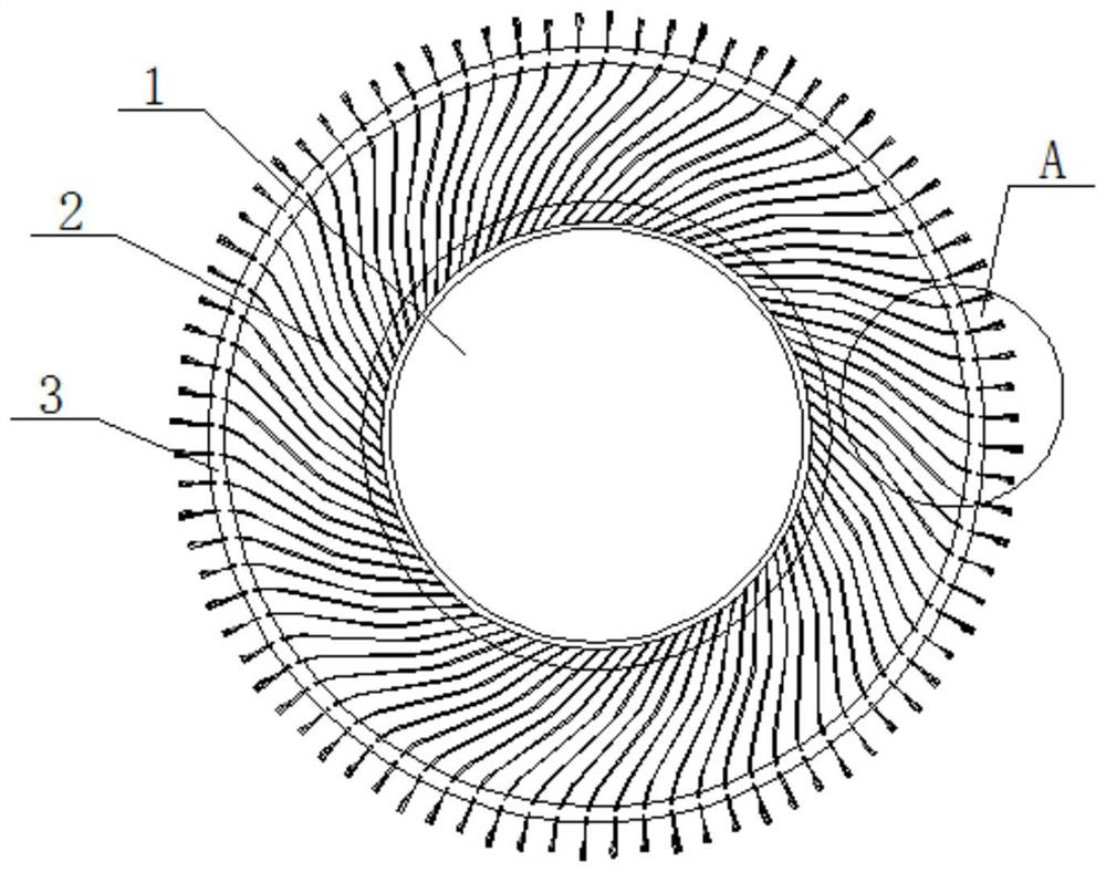
[0036] In the present application, the metal blade 2 includes a first metal blade 21 and a second metal blade 22 with the same structure and different lengths. The fan wheel of the present application includes a hub 1, a metal fan blade 2 and a connecting ring 3. The proximal end of the metal fan blade 2 is connected to the hub, and the distal end is connected to the connecting ring 3 to ensure the overall structural stability of the hub.

[0037] Specifically, the metal fan blade 2 includes a first metal blade 21 and a second metal blade 22 with different lengths. The first metal blade 21 and the second metal blade 22 are alternately distributed on the outer circumference of the hub 1. The first metal blade 21 and The intervals between the second metal blades 22 are the same. Through the design of the first metal blade 21 and the second metal blade 22 with different lengths, the swept area of ​​the adjacent blades is different, and the fan can not only maintain balance during...

Embodiment 2

[0043] The difference between this embodiment and Embodiment 1 is that the metal blades of this embodiment include metal blades with three lengths. like Figure 4 As shown, the metal fan blade 2 includes a first metal blade 21 , a second metal blade 22 and a third metal blade 23 which have the same structure and increase in length in sequence. The proximal ends of the first metal blade 21 , the second metal blade 22 , and the third metal blade 23 are connected with the hub 1 , and the distal ends are connected with the connecting ring 3 .

[0044] By adopting the design of the first metal blade 21, the second metal blade 22 and the third metal blade 23, the fan can not only maintain a balance during operation, but also avoid the same frequency of blade sweeping vibration, solve the energy concentration at a single frequency, and greatly Reduced noise from fan operation.

[0045] Similarly, in this embodiment, the middle parts of the ends of the windward surfaces of the first...


PUM


Abstract

The invention discloses a metal fan wheel which comprises a hub, metal blades and a connecting ring, the metal blades comprise a plurality of first metal blades and a plurality of second metal blades, the first metal blades and the second metal blades are different in length, and the first metal blades and the second metal blades are alternately and evenly distributed on the periphery of the hub; the connecting ring and the hub are coaxially arranged, and the connecting ring is connected with the bottom face of the first metal blade and the bottom face of the second metal blade. The first metal blades and the second metal blades which are different in length are designed along the periphery of the hub, so that the wind sweeping areas of the adjacent blades are different, and the first metal blades and the second metal blades are arranged in the circumferential direction of the hub in a staggered mode and are evenly distributed, so that the fan blades can be kept balanced during operation, and the wind sweeping area of the fan blades is increased. And the wind sweeping vibration frequencies of the blades are prevented from being consistent, the problem of energy concentration under single frequency is solved, and the noise generated by fan operation is greatly reduced.

Description

technical field [0001] The invention relates to the technical field of fans, in particular to a metal fan wheel, a fan and an electronic product. Background technique [0002] In order to ensure the normal operation of high-power components, electronic products such as computers are usually equipped with radiators, which include metal radiators or plastic radiators. Among them, the metal radiator is recognized by the majority of manufacturers because of its long service life and not easy to deform. [0003] However, the current metal radiator has a problem of energy concentration at a single frequency during operation due to the large air volume of the fan blades, which causes the fan to generate noise. How to solve the noise problem of the fan has always been our research problem. SUMMARY OF THE INVENTION [0004] The purpose of the present invention is to provide a metal fan wheel, a fan and an electronic product, so as to solve the problem of noise when the fan is run...

Claims


Application Information

Patent Timeline
Patent Type & Authority Applications(China)
IPC IPC(8): F04D29/26F04D29/66F04D29/02F04D25/08G06F1/20
CPCF04D29/26F04D29/666F04D29/667F04D29/023F04D25/08G06F1/20
Inventor 何克锋李龙
Owner 昆山品岱电子有限公司
Learn More