Moving die plate of injection molding machine and injection molding machine

A mobile template and injection molding machine technology, applied in the field of injection molding machines, can solve problems such as unreasonable layout of machine hinge joints, increase the weight of mobile templates, increase the amount of matrix materials, etc., to reduce the application of materials, reduce weight, and reduce weight Effect

Inactive Publication Date: 2017-06-30
广东佳明机器有限公司
View PDF9 Cites 3 Cited by
  • Summary
  • Abstract
  • Description
  • Claims
  • Application Information

AI Technical Summary

Problems solved by technology

[0003] Chinese patent: 201220637205.7 discloses a mobile template of an injection molding machine. The hinged connection seat of the movable template of the injection molding machine is fixed on four cylinders (guiding cylinders) with pull rod holes, and a cavity is provided between the hinged connection seat and the base. , when pulling or pushing the mobile formwork, the force is transmitted to the four columns with tie rod holes connected to it through the machine hinge joint seat, because the connection between the machine hinge joint seat and the four cylinders with tie rod holes The contact surface is limited, so the force it bears is too concentrated on the limited contact point, and it is easy to deform or break; the design of its single hinge point is also not conducive to the dispersion of force, so that the force is too concentrated, so it is easy to deform or break
The unreasonable arrangement of the guide cylinders, hinged joints and other parts on the mobile formwork in the prior art increases the amount of material of the matrix that these parts must carry, which undoubtedly increases the weight of the mobile formwork and brings inconvenience to its processing

Method used


Image

  • Moving die plate of injection molding machine and injection molding machine
  • Moving die plate of injection molding machine and injection molding machine
  • Moving die plate of injection molding machine and injection molding machine

Examples


Embodiment Construction

[0024] The present invention will be described in further detail below in conjunction with the accompanying drawings.

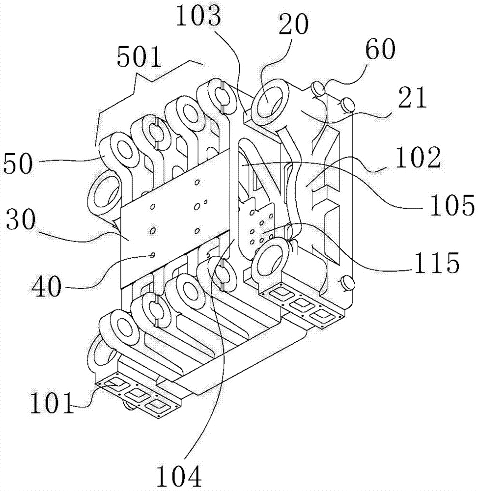
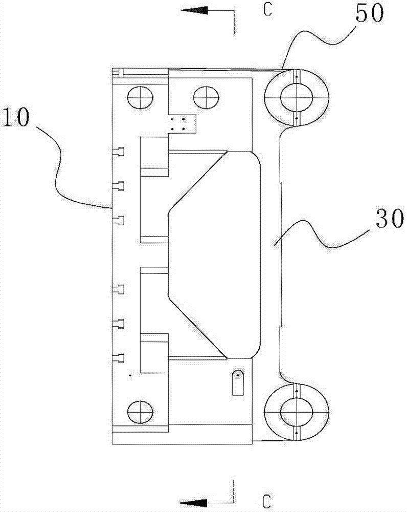
[0025] Figure 1~2 A moving platen of an injection molding machine according to an embodiment of the present invention is schematically shown. As shown in the figure, the device includes: a module base 10 , a guide cylinder 21 provided with a guide post hole 20 , a mounting plate 30 of an ejection mechanism, and a machine hinge connection seat system 501 .

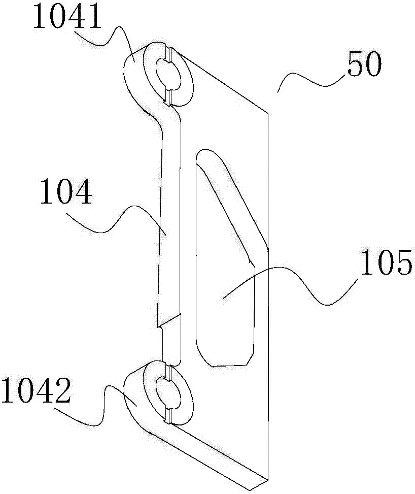
[0026] The module base 10 is used as a material for carrying the guide cylinder 21 and the machine-hinged connection seat system 501, and its cross-section is square. On the four corners of the base body 10 , and the machine-hinged connection seat system 501 is arranged between any two adjacent guide cylinders 21 . The machine-hinge joint system 501 is made up of machine-hinge joint 50, and machine-hinge joint 50 is provided with hinge head, and the hinge joint of machine-hinge joint 50 appears in pairs...


PUM


Abstract

The invention discloses a moving die plate of an injection molding machine and the injection molding machine. The moving die plate of the injection molding machine comprises a die block base body, a guide cylinder provided with a guide column hole, an ejecting mechanism mounting plate and mechanically reamed connecting bases, wherein the guide cylinder and the mechanically reamed connecting bases are separately arranged on the die block base body, the mechanically reamed connecting bases are arranged in pairs, and a first reinforcing rib plate is connected between each pair of mechanically reamed connecting bases; the ejecting mechanism mounting plate is arranged on the first reinforcing rib plates; and the mechanically reamed connecting bases are directly connected to the die block base body, and no gaps are arranged between the mechanically reamed connecting bases and the die block base body, so that the mechanically reamed connecting bases cannot easily deform or crack when subjected to tensile force or pressure. Therefore, the strength and the rigidity of the mechanically reamed connecting bases can be increased; and at the same time, by adopting reasonable mechanism design, used materials are reduced, and the weight of the moving die plate is reduced, so that the moving die plate is more flexible in running and more convenient to machine.

Description

technical field [0001] The invention relates to the field of injection molding machines, in particular to the field of parts of large injection molding machines and injection molding equipment containing the parts. Background technique [0002] The mobile template of the injection molding machine moves on the guide rod, and its moving power comes from the hydraulic rod or connecting rod connected to it, and this connection often adopts a hinged method, that is, an organic hinged connection seat is provided on the mobile template for the hydraulic rod or connecting rod. Connecting rod connection, it can be seen that when the mobile formwork moves along the guide rod, the hinged connection seat of the machine is a direct force-bearing part. [0003] Chinese patent: 201220637205.7 discloses a mobile template of an injection molding machine. The hinged connection seat of the movable template of the injection molding machine is fixed on four cylinders (guiding cylinders) with pul...

Claims


Application Information

Patent Timeline
Patent Type & Authority Applications(China)
IPC IPC(8): B29C45/17
CPCB29C45/1761B29C45/1744
Inventor 李裔强方来
Owner 广东佳明机器有限公司
Why Eureka
Try Eureka