Air source heat pump air heater system

A technology of air source heat pump and hot air blower, applied in the field of heat pump, can solve the problems of decreased working stability of equipment, blockage of tuyere, easy accumulation of impurities in the tuyere, etc., so as to improve the diversion rate and avoid long-term use.

Inactive Publication Date: 2022-07-29
李新国
View PDF1 Cites 0 Cited by
  • Summary
  • Abstract
  • Description
  • Claims
  • Application Information

AI Technical Summary

Problems solved by technology

[0004] The purpose of the present invention is to solve the problem that after the current heat pump air blower is used for a long time, the tuyere is easy to accumulate impurities, resulting in blockage of the tuyere, resulting in poor air supply of the whole hot air, and at the same time, the equipment will vibrate when it is working, and due to the heat There is a fixed rigid connection between the fan and the installation surface, which causes the equipment to work for a long time and the vibration cannot be relieved, resulting in damage to the equipment and a short service life. Some equipment is equipped with a shock absorbing spring to alleviate the vibration, but when the equipment vibrates When it is larger, due to the elastic force of the spring, the equipment may vibrate more and more. Not only can it not absorb the vibration, but it may also reduce the working stability of the equipment. An air source heat pump air blower system is proposed

Method used


Image

  • Air source heat pump air heater system
  • Air source heat pump air heater system
  • Air source heat pump air heater system

Examples


Embodiment Construction

[0042] The technical solutions in the embodiments of the present invention will be clearly and completely described below with reference to the accompanying drawings in the embodiments of the present invention. Obviously, the described embodiments are only a part of the embodiments of the present invention, but not all of the embodiments. Based on the embodiments of the present invention, all other embodiments obtained by those of ordinary skill in the art without creative efforts shall fall within the protection scope of the present invention.

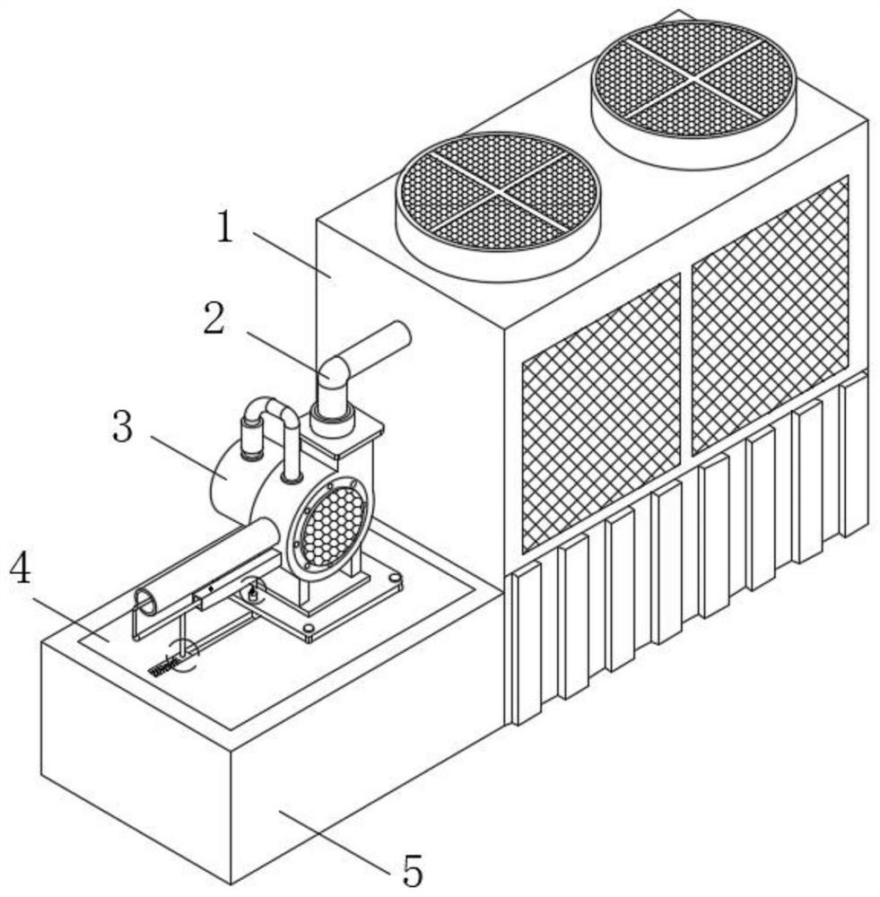
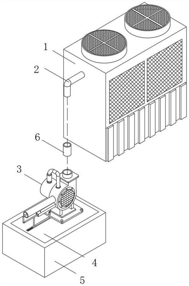
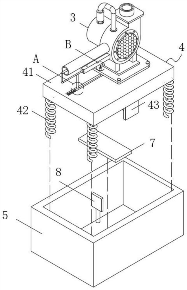
[0043] see Figure 1-10 , the present invention provides a technical solution: an air source heat pump heat blower system, including a heat pump host 1, a heat source conduit 2 and a mounting seat 5 are fixedly installed on one side outer wall of the heat pump host 1, and the heat source conduit 2 is One end is connected with a hot air blower assembly 3, the hot air blower assembly 3 is used for hot air transportation, the inside of t...


PUM


Abstract

The invention discloses an air source heat pump hot-air blower system, which belongs to the technical field of heat pumps and comprises a heat pump host, a heat source conduit and a mounting seat are fixedly mounted on the outer wall of one side of the heat pump host, one end of the heat source conduit is connected with a hot-air blower assembly, and the hot-air blower assembly is used for conveying hot air. A damping assembly is arranged in the mounting seat, the damping assembly is used for stable work damping of the hot air machine assembly, the hot air machine assembly is fixedly mounted on the damping assembly, the hot air machine assembly comprises a machine body, a base is fixedly mounted at the bottom of the machine body, and a hot air guide pipe and a square air pipe are fixedly mounted on the side wall of the machine body; according to the hot air system, the cleaning flow guide assembly and the driving assembly are arranged, through the design, part of wind power of the hot air machine assembly is used for driving, through linkage action between structures, the hot air supply speed rate can be effectively guaranteed, meanwhile, the hot air supply smoothness is guaranteed, and the use effect and efficiency of the hot air system are improved.

Description

technical field [0001] The invention belongs to the technical field of heat pumps, and in particular relates to an air source heat pump heat blower system. Background technique [0002] A heat pump is a common heat energy transfer device. A heat pump is mainly a mechanical device that forces heat to flow from a low temperature object to a high temperature object in a reverse cycle. It only consumes a small amount of reverse cycle net work to obtain a large amount of heat supply. It can effectively use the low-grade heat energy that is difficult to apply to achieve the purpose of energy saving. When the heat pump is used, when hot air is required, the hot air system needs to be used. [0003] Chinese patent discloses (CN111829057A) an air energy heat pump hot air blower, including a body, a fixing column is fixedly connected to the middle of the inner cavity of the body, and a support plate is fixedly connected to the inner cavity of the body on the right side of the fixing c...

Claims


Application Information

Patent Timeline
Patent Type & Authority Applications(China)
IPC IPC(8): F24H4/06F24H9/06F16F15/067B01D46/681
CPCF24H4/06F24H9/06F16F15/067
Inventor 李新国
Owner 李新国
Why Eureka
Try Eureka