OLED screen on-line fluorescence microscope inspection machine

A fluorescence microscope and inspection machine technology, applied in fluorescence/phosphorescence, material analysis through optical means, material excitation analysis, etc., can solve the problems of detection camera start-up time lag, position deviation, workpiece collision damage, etc., to reduce air transportation The effect of doing time, shortening the distance of exercise, and saving time

Active Publication Date: 2022-07-29
江苏才道精密仪器有限公司
View PDF12 Cites 0 Cited by
  • Summary
  • Abstract
  • Description
  • Claims
  • Application Information

AI Technical Summary

Problems solved by technology

[0003] After the OLED screen is manufactured, it needs to be inspected with a fluorescence microscope, and the inspection of large-size OLED screens is limited to single-sided, low-efficiency mode, so the detection area is less, and the possibility of detection error is greater
Moreover, the shape of the gantry in the existing OLED screen detection equipment is set as an I-shaped, so only one-sided detection can be performed on the OLED screen. After the single-sided detection is completed, the workpiece needs to be flipped and re-detected. Such a setting Not only will it waste a lot of time, but it is also prone to collision damage to the workpiece during the flipping and transfer process. At this stage, the OLED screen is usually manually placed by the worker, and after being pushed to the designated position, the detection camera will move for detection
This mode is not only prone to position deviation when placed, which affects shooting and detection; moreover, the start-up time of the detection camera is too late, and the movement and reset consume a lot of time, which is inefficient. For this reason, we propose an OLED screen online fluorescence microscope inspection machine

Method used


Image

  • OLED screen on-line fluorescence microscope inspection machine
  • OLED screen on-line fluorescence microscope inspection machine
  • OLED screen on-line fluorescence microscope inspection machine

Examples


Embodiment Construction

[0029] The technical solutions in the embodiments of the present invention will be clearly and completely described below with reference to the accompanying drawings in the embodiments of the present invention. Obviously, the described embodiments are only a part of the embodiments of the present invention, but not all of the embodiments. Based on the embodiments of the present invention, all other embodiments obtained by those of ordinary skill in the art without creative efforts shall fall within the protection scope of the present invention.

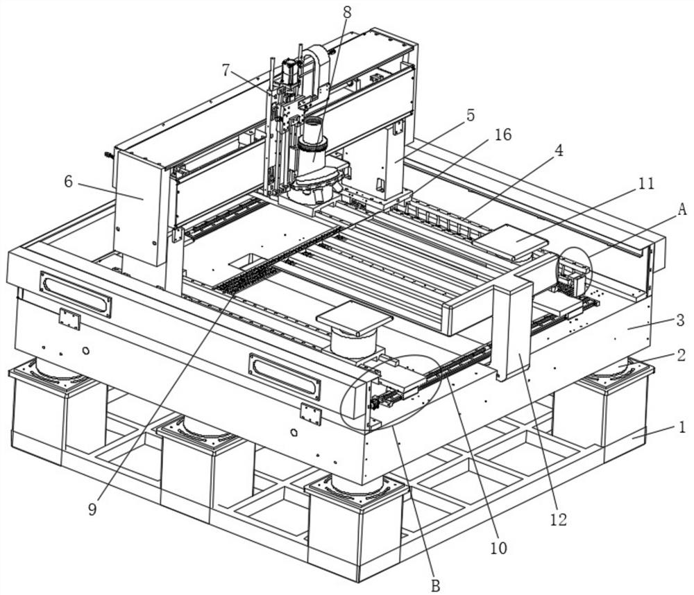
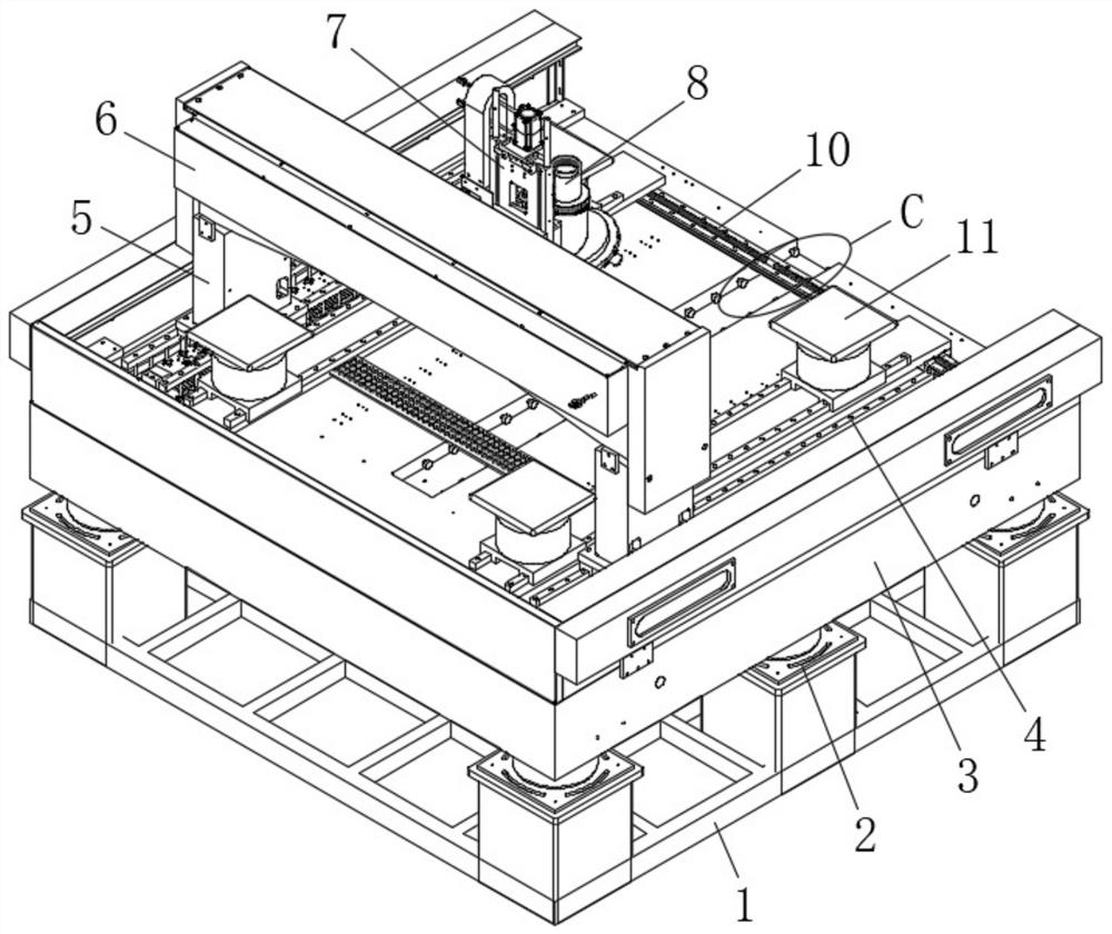
[0030] see figure 1, the present invention provides a technical solution: an OLED screen online fluorescence microscope inspection machine, comprising a bottom plate 1, the top of the bottom plate 1 is fixedly connected with a substrate 3 through four groups of support columns 2, and both sides of the top of the substrate 3 are A first conveying mechanism 4 that moves in the X direction is fixedly installed, a rectangular gantry 5 is ...


PUM


Abstract

The OLED screen online fluorescence microscope inspection machine comprises a bottom plate, the top of the bottom plate is fixedly connected with a base plate through four sets of supporting columns, the two sides of the top of the base plate are each fixedly provided with a first conveying mechanism moving in the X direction, and the tops of the two sets of first conveying mechanisms are fixedly connected with a rectangular portal frame. A traditional I-shaped portal frame form is abandoned, the rectangular portal frame is adopted, the first guide rail supporting nails are arranged for installation and suspension, therefore, the motion space of the rectangular portal frame can be guaranteed, collision with a workpiece is avoided, the top detector and the bottom detector are arranged on the upper portion and the lower portion of the rectangular portal frame correspondingly, and rapid photographing and rapid detection can be achieved; the detection area is enlarged, and the arranged first adjusting mechanism and second adjusting mechanism can perform left-right and up-down movement adjustment on the top detector, so that the accuracy and comprehensiveness of OLED screen top detection can be ensured.

Description

technical field [0001] The invention relates to the technical field of OLED screen detection, in particular to an OLED screen online fluorescence microscope inspection machine. Background technique [0002] OLED screen is a new type of imaging electronic device made of light-emitting diodes arranged in sequence. Due to its high brightness, wide viewing angle and long life, it is being widely used in outdoor advertising screens and other products. [0003] After the OLED screen is manufactured, it needs to be tested by a fluorescence microscope, and the detection of large-size OLED screens is limited to a single-sided, low-efficiency mode, so the detection area is small, and there is a possibility of detection errors. larger. In addition, in the existing OLED screen detection equipment, the gantry shape is set to I-shaped, so only one-sided detection of the OLED screen can be performed. Such a setting requires the workpiece to be flipped and re-detected after the single-sid...

Claims


Application Information

Patent Timeline
IPC IPC(8): G01N21/64G01N21/01
CPCG01N21/6458G01N21/01
Inventor 任勇马观岚刘佳仪郁文韬施坤昊胡均萱
Owner 江苏才道精密仪器有限公司
Why Eureka
Try Eureka