
Optical cable ground laying optical fiber protection device

A technology for optical fiber protection and ground, applied in the direction of fiber mechanical structure, etc., can solve the problems of easy breakage of optical fiber, difficulty in flexible disassembly, inconvenient use, etc., and achieve the effect of reducing pressure damage, good protection effect, and reasonable design

Pending Publication Date: 2022-07-29
浙江振东光电科技有限公司
View PDF1 Cites 0 Cited by
  • Summary
  • Abstract
  • Description
  • Claims
  • Application Information

AI Technical Summary

Problems solved by technology

[0004] The above-mentioned solution solves to a certain extent the problems in the prior art that the optical fiber protective sleeve is not easy to be flexibly disassembled and inconvenient to use after being connected, but this solution still has many deficiencies, for example: the protective sleeve cannot withstand the Vertical pressure, and the optical fiber itself is too fragile and easy to break, the optical fiber is easy to withstand high pressure and damage, affecting communication, and the protection effect is not good

Method used


Image

  • Optical cable ground laying optical fiber protection device
  • Optical cable ground laying optical fiber protection device
  • Optical cable ground laying optical fiber protection device

Examples


Embodiment Construction

[0026] The present invention will be described in further detail below with reference to the accompanying drawings and specific embodiments.

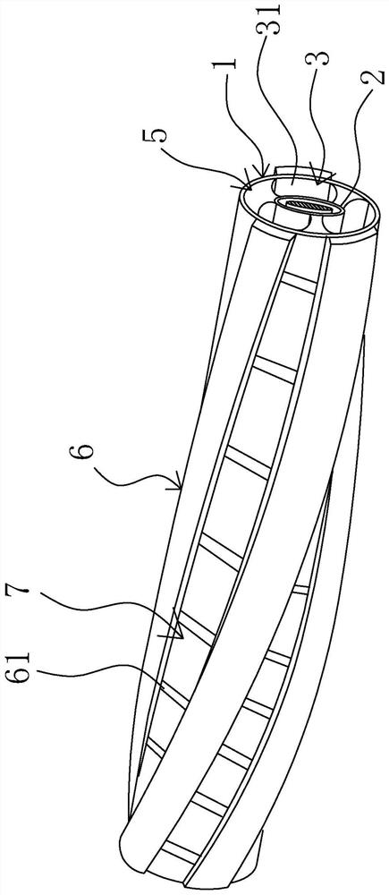
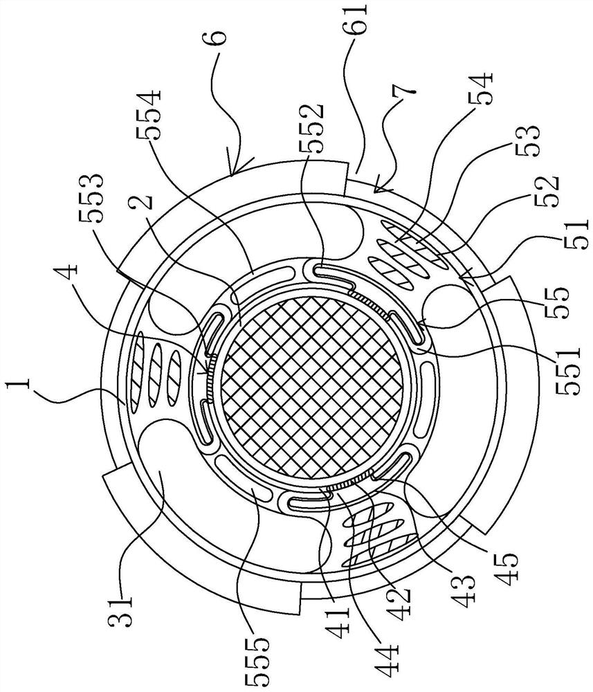
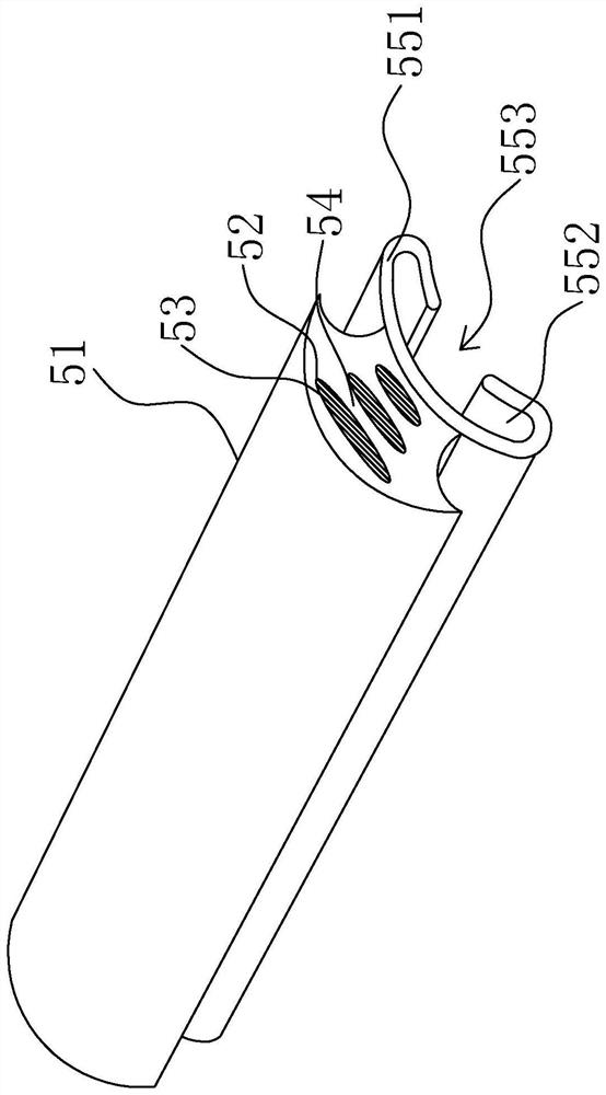
[0027] like Figure 1-8As shown in the figure, the optical fiber protection device for laying optical fibers on the ground of the optical cable includes a protective outer tube 1, and a protective inner tube 2 for loading optical fibers is provided on the circumferential inner side of the protective outer tube 1, and a support is provided between the protective inner tube 2 and the protective outer tube 1 Gap 3, the support gap 3 is provided with a number of elastic pressure-relief mechanisms 5, one end of which is fixedly connected to the circumferential inner wall of the protective outer tube 1 and the other end is connected with the protective inner tube 2 through the plug connection assembly 4, and the protective outer tube 1 The peripheral outer wall is provided with a plurality of anti-compression and shock-absorbing components 6 ...


PUM


Abstract

The invention relates to an optical cable ground laying optical fiber protection device. The optical fiber protection sleeve solves the problem that an optical fiber protection sleeve in the prior art is poor in protection effect. The device comprises a protective outer tube, a protective inner tube used for loading optical fibers is arranged on the circumferential inner side of the protective outer tube, a supporting gap is formed between the protective inner tube and the protective outer tube, and a plurality of elastic pressure buffering mechanisms with one ends fixedly connected with the circumferential inner wall of the protective outer tube and the other ends connected with the protective inner tube through insertion connection assemblies are arranged in the supporting gap. And a plurality of pressure-resistant damping assemblies are spirally arranged on the outer wall of the protective outer pipe in the circumferential direction, and a pressure conduction mechanism is arranged between every two adjacent pressure-resistant damping assemblies and located on the outer wall of the protective outer pipe. The optical fiber protection device has the advantages that the protection effect is good, and damage of external pressure to the optical fiber is effectively reduced.

Description

technical field [0001] The invention relates to the technical field of optical fiber protection, in particular to an optical fiber protection device for laying optical cables on the ground. Background technique [0002] Optical fiber, short for optical fiber, is a fiber made of glass or plastic that acts as a light-transmitting tool. Optical fibers are widely used in various engineering fields because of their unique advantages such as strong chemical corrosion resistance, good electrical insulation performance, small size, light weight, strong adaptability, and low cost. The laying of optical cables is the first and key step in engineering applications, so the protection of optical fibers during the laying process is the top priority in the entire project. Most of the current optical cable ground laying sites are manually compared, and the optical cable is placed in it with bricks with reserved slots, and then the bricks are tamped on the ground by knocking from above. Ex...

Claims


Application Information

Patent Timeline
Patent Type & Authority Applications(China)
IPC IPC(8): G02B6/44
CPCG02B6/443
Inventor 雷诚秦一涛
Owner 浙江振东光电科技有限公司
Learn More