Unsupervised fault diagnosis method and device for mechanical equipment and medium

A technology of fault diagnosis and mechanical equipment, applied in the direction of neural learning methods, computer components, instruments, etc., can solve problems such as difficult fault diagnosis, lack of adaptability of diagnosis effect, non-stationary vibration signal and large noise interference, etc., to achieve The effect of improving clustering performance

Pending Publication Date: 2022-07-29
SOUTH CHINA UNIV OF TECH
View PDF0 Cites 0 Cited by
  • Summary
  • Abstract
  • Description
  • Claims
  • Application Information

AI Technical Summary

Problems solved by technology

However, for unsupervised intelligent fault diagnosis, the existing methods still have the following limitations: 1) The working conditions of mechanical equipment are changeable, and vibration signals often have strong non-stationarity and large noise interference. Traditional signal processing methods need to rely on Expert diagnostic knowledge is used for feature extraction and selection. Whether its diagnostic performance is excellent or not depends on the quality of feature selection, so its diagnostic effect lacks strong adaptability and is easy to "varie with objects"; 2) Deep learning methods can be effective End-to-end adaptive extraction of discriminative features, however, the existing deep learning diagnosis methods are usually based on supervised learning methods, which need to ensure that labeled and balanced data samples participate in training, which cannot be well suited for unsupervised fault feature learning and clustering ; 3) Although deep neural networks such as DBN and SAE can stack multiple restricted Boltzmann machines / autoencoders and use greedy algorithms for unsupervised deep learning and feature extraction, the above learning methods have not fully considered Input the prior information of the sample itself, so it is difficult to effectively deal with the problem of fault diagnosis under the changing conditions of complex mechanical equipment

Method used


Image

  • Unsupervised fault diagnosis method and device for mechanical equipment and medium
  • Unsupervised fault diagnosis method and device for mechanical equipment and medium
  • Unsupervised fault diagnosis method and device for mechanical equipment and medium

Examples


Embodiment Construction

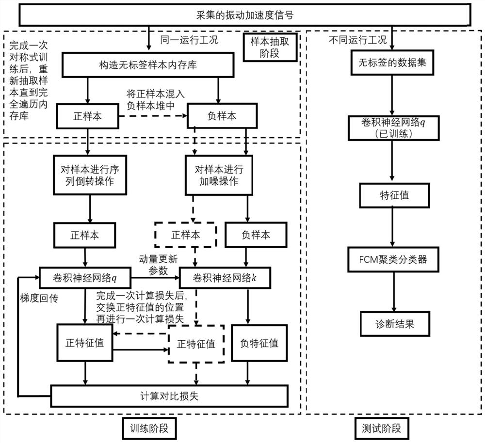
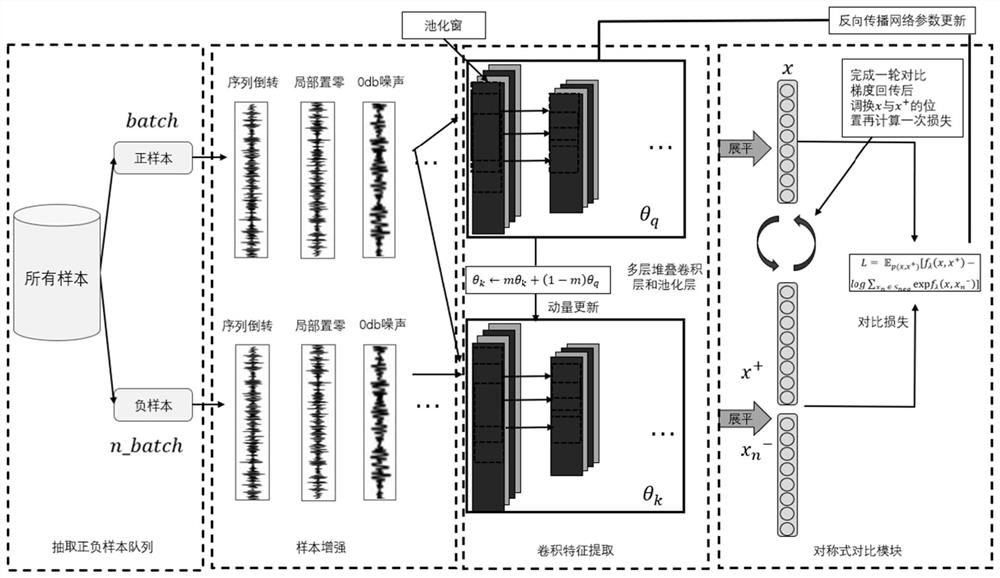
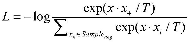
[0043] The following describes in detail the embodiments of the present invention, examples of which are illustrated in the accompanying drawings, wherein the same or similar reference numerals refer to the same or similar elements or elements having the same or similar functions throughout. The embodiments described below with reference to the accompanying drawings are exemplary, only used to explain the present invention, and should not be construed as a limitation of the present invention. The numbers of the steps in the following embodiments are set only for the convenience of description, and the sequence between the steps is not limited in any way, and the execution sequence of each step in the embodiments can be adapted according to the understanding of those skilled in the art Sexual adjustment.

[0044] In the description of the present invention, it should be understood that the azimuth description, such as the azimuth or position relationship indicated by up, down, fr...


PUM


Abstract

The invention discloses an unsupervised fault diagnosis method and device for mechanical equipment and a medium. The method comprises the following steps: acquiring a positive sample and a negative sample; constructing feature extractors q and k, and taking a positive sample as the input of q; taking the positive sample and the negative sample as the input of k; a high-dimensional feature x is obtained through a feature extractor q, and high-dimensional features x + and xn-are obtained through a feature extractor k; calculating comparison loss according to the high-dimensional features x, x + and xn-, performing gradient return, and reversely updating the parameter theta q; updating the parameter theta k according to the parameter theta q; performing iterative training on the feature extractor q to obtain a trained feature extractor q; and inputting the original sample data into q, obtaining a high-dimensional characteristic value, carrying out clustering processing, obtaining three evaluation indexes, and realizing fault diagnosis according to the three evaluation indexes. According to the invention, discrimination features of different types can be fully utilized, and the unsupervised fault clustering performance of the network is improved; the method can be widely applied to the rotating machinery intelligent fault diagnosis field.

Description

technical field [0001] The invention relates to the field of intelligent fault diagnosis of rotating machinery, in particular to a method, device and medium for unsupervised fault diagnosis of mechanical equipment. Background technique [0002] For manufacturing enterprises, equipment fault status monitoring and prognostics health management (PHM) is an important means to avoid safety accidents and improve the operation efficiency of enterprises. It is also an important part of realizing equipment intelligence and promoting the transformation of manufacturing industry. [0003] Rotating machinery, which is closely related to industrial manufacturing, is the core equipment produced in the fields of aerospace, automobile manufacturing, and rail transit. Because it usually serves in harsh environments such as high load, high speed, and high temperature, its key parts such as bearings and gears are easily error occured. Therefore, how to effectively process a large amount of me...

Claims


Application Information

Patent Timeline
IPC IPC(8): G06K9/00G06K9/62G06N3/04G06N3/08
CPCG06N3/08G06N3/045G06F2218/08G06F2218/12G06F18/213G06F18/23G06F18/241
Inventor 李巍华何琛陈祝云
Owner SOUTH CHINA UNIV OF TECH
Why Eureka
Try Eureka