Driving method of LCD (Liquid Crystal Display) driving circuit

A driving circuit and driving method technology, applied in the field of LCD driving, can solve the problem of high power consumption, and achieve the effects of stable voltage, stable working voltage and reduced power consumption

Pending Publication Date: 2022-07-29
江苏集萃智能集成电路设计技术研究所有限公司
View PDF0 Cites 0 Cited by
  • Summary
  • Abstract
  • Description
  • Claims
  • Application Information

AI Technical Summary

Problems solved by technology

However, when the existing LCD drive circuit is actually used, the bandgap reference circuit is always enabled to work, that i

Method used


Image

  • Driving method of LCD (Liquid Crystal Display) driving circuit
  • Driving method of LCD (Liquid Crystal Display) driving circuit
  • Driving method of LCD (Liquid Crystal Display) driving circuit

Examples


Embodiment Construction

[0025] The present invention will now be described in further detail with reference to the accompanying drawings. These drawings are all simplified schematic diagrams, and only illustrate the basic structure of the present invention in a schematic manner, so they only show the structures related to the present invention.

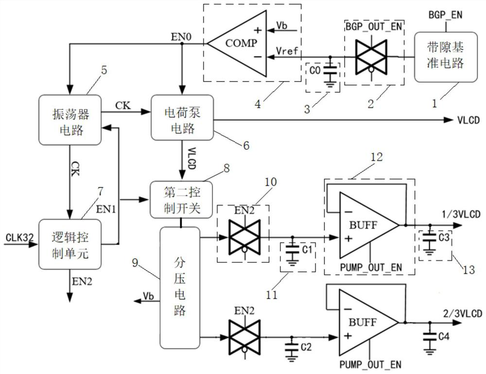
[0026] like figure 1 As shown, the driving method of the LCD driving circuit, wherein the LCD driving circuit includes a bandgap reference circuit 1, a first control switch 2, a first energy storage unit 3, a comparison unit 4, an oscillator circuit 5, a charge pump circuit 6, a logic control Unit 7, second control switch 8, voltage divider circuit 9, two voltage output branches, each voltage output branch includes a third control switch 10, a second energy storage unit 11, a buffer 12 and a third energy storage unit 13;

[0027] The voltage output terminal of the bandgap reference circuit 1 is electrically connected to the input terminal of the first cont...


PUM


Abstract

The invention relates to the technical field of LCD driving, and discloses a driving method of an LCD driving circuit, in the method, a first energy storage unit can be periodically charged by periodically inputting a first enable signal to a band-gap reference circuit and inputting a second enable signal to a first control switch; the first energy storage unit provides reference voltage for the negative input end of the comparison unit, so that the working time of the band-gap reference circuit can be shortened, and the power consumption is further reduced; according to the charge pump circuit, the second energy storage unit can be periodically charged by periodically controlling the on-off of the second control switch and the third control switch, then the second energy storage unit charges the third energy storage unit by periodically inputting a third enable signal to the buffer, and finally the third energy storage unit provides the working voltage of the LCD, so that the working time of the charge pump circuit can be shortened, and the working efficiency is improved. And power consumption is reduced.

Description

technical field [0001] The invention relates to the technical field of LCD driving, in particular to a driving method of an LCD driving circuit. Background technique [0002] In electronic products, liquid crystal screens or LCD display screens are often used for information display and human-computer interaction, and have become an indispensable component of most electronic products. At present, the existing LCD driving circuits often use a charge pump circuit to provide a reference voltage, and then control the operation of the charge pump based on the comparison result between the reference voltage and the detection point voltage, so that the charge pump generates a driving voltage for driving the LCD display. However, when the existing LCD driving circuit is actually used, the bandgap reference circuit is always enabled to work, that is, a stable bandgap reference voltage is always output to provide to other circuit modules, and the power consumption is relatively high. ...

Claims


Application Information

Patent Timeline
IPC IPC(8): G09G3/36
CPCG09G3/36G09G2310/0264G09G2330/021Y02D10/00
Inventor 杨金烨戚祎薛中赵海
Owner 江苏集萃智能集成电路设计技术研究所有限公司
Why Eureka
Try Eureka