Antenna assembly, electronic equipment and control method thereof

A technology of antenna components and electronic equipment, which is applied to antennas, antenna supports/mounting devices, and devices that enable antennas to work in different bands at the same time, and can solve problems such as poor antenna performance, performance discounts, and easy handling of antennas. To achieve the effect of improving radiation performance

Pending Publication Date: 2022-07-29
GUANGDONG OPPO MOBILE TELECOMM CORP LTD
0 Cites 0 Cited by

AI-Extracted Technical Summary

Problems solved by technology

[0002] With the continuous improvement of mobile phone performance, more and more mobile games have entered people's entertainment life, and mobile games such as King of Glory have higher and higher requirements for mobile phone signal when holding a horizontal screen, while traditional In the antenna design of the mobile phone, the LTE antenna is generally located on the top and bottom of the mobile phone, so that the performance of the antenna is poor when the horizontal screen is held in the ...

Method used

Electronic equipment in the present embodiment, its antenna component is by setting switch, and same radiator can produce two kinds of radiation patterns, because the radiation branches of two kinds of patterns are different, can guarantee to hold in horizontal screen hand-held and single-handed hand-held The antenna will not be held at all times, so that both usage scenarios can be taken into consideration, and the radiation performance of the antenna can be improved.
The antenna assembly that the embodiment of the present application provides, by arranging switching switch, same radiator can produce two kinds of radiation modes, because the radiation branches of two kinds of modes are different, can guarantee that when holding in horizontal screen hand-held and single-handed hand-held Both will not be caught, so that both usage scenarios can be considered, and the radiation performance of the antenna can b...

Abstract

The invention provides an antenna assembly, electronic equipment and a control method thereof. The antenna assembly comprises a first radiator, a change-over switch, a grounding circuit and a first feed source. The first radiator is provided with a first connection point and a second connection point at an interval. The first feed source is connected with the first connection point, one end of the change-over switch is connected with the second connection point, the other end of the change-over switch is connected with the grounding circuit, and the change-over switch is used for switching different branches of the grounding circuit to be connected with the second connection point of the first radiator. Therefore, the switching of the radiation mode of the first radiator is realized. According to the antenna assembly provided by the embodiment of the invention, the change-over switch is arranged, the same radiator can generate two radiation modes, and the radiation branches of the two modes are different, so that the antenna cannot be held when the antenna is held by a horizontal screen or a single hand, two use scenes are considered, and the radiation performance of the antenna is improved.

Application Domain

Technology Topic

Image

  • Antenna assembly, electronic equipment and control method thereof
  • Antenna assembly, electronic equipment and control method thereof
  • Antenna assembly, electronic equipment and control method thereof

Examples

  • Experimental program(1)

Example Embodiment

[0024] The present invention will be further described in detail below with reference to the accompanying drawings and embodiments. It is particularly pointed out that the following examples are only used to illustrate the present invention, but do not limit the scope of the present invention. Likewise, the following embodiments are only some rather than all embodiments of the present invention, and all other embodiments obtained by those of ordinary skill in the art without creative work fall within the protection scope of the present invention.
[0025] Reference herein to an "embodiment" means that a particular feature, structure, or characteristic described in connection with the embodiment can be included in at least one embodiment of the present invention. The appearances of the phrase in various places in the specification are not necessarily all referring to the same embodiment, nor a separate or alternative embodiment that is mutually exclusive of other embodiments. It is explicitly and implicitly understood by those skilled in the art that the embodiments described herein may be combined with other embodiments.
[0026] "Electronic equipment" (or simply "terminal") as used herein includes, but is not limited to, is configured to be connected via a wired line (eg, via a public switched telephone network (PSTN), digital subscriber line (DSL), digital cable, Direct cable connection, and/or another data connection/network) and/or via (eg, for cellular networks, wireless local area networks (WLAN), digital television networks such as DVB-H networks, satellite networks, AM-FM broadcast transmitters , and/or another communication terminal's) wireless interface to receive/send communication signals. A communication terminal arranged to communicate through a wireless interface may be referred to as a "wireless communication terminal", "wireless terminal" or "mobile terminal". Examples of mobile terminals include, but are not limited to, satellite or cellular telephones; Personal Communication System (PCS) terminals that may combine cellular radio telephones with data processing, fax, and data communication capabilities; may include radio telephones, pagers, Internet/Intranet access , a PDA with a web browser, memo pad, calendar, and/or a global positioning system (GPS) receiver; and conventional laptop and/or palm receivers or other electronic devices including radiotelephone transceivers. A mobile phone is an electronic device equipped with a cellular communication module.
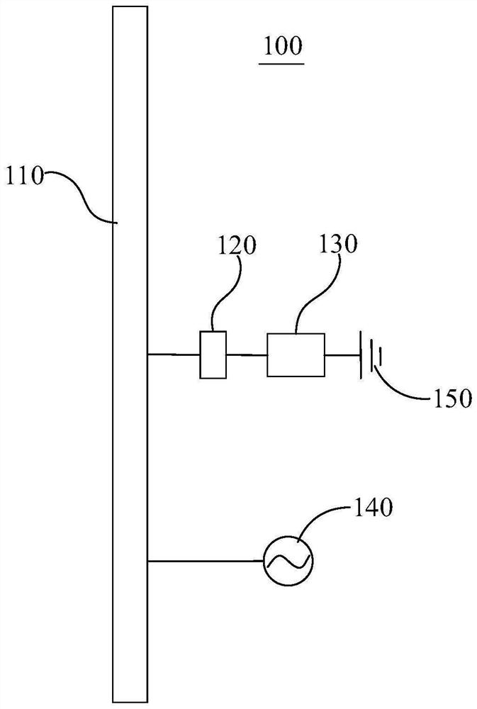
[0027] In order to prevent the antenna from being blocked by the user's hand, the conventional technical solution is generally to set up multiple antennas, and then detect the signal radiation intensity of different antennas (that is, when they are blocked), and then switch different antennas to access the radiation circuit. ; In addition, there are some conventional technical solutions to connect the different feeding points of the antenna radiator into the radiating circuit.
[0028] In comparison, the technical solutions in the embodiments of the present application are as follows.
[0029] see figure 1 , figure 1 This is a schematic structural diagram of an embodiment of an antenna assembly used in an electronic device in the present application; it should be noted that the electronic device in the present application may include mobile phones, tablet computers, notebook computers, wearable devices and other electronic devices with radio frequency signal sending and receiving functions . The antenna assembly 100 for an electronic device includes, but is not limited to, a first radiator 110 , a switch 120 , a ground circuit 130 and a first feed source 140 . It should be noted that the terms "comprising" and "having" and any modifications thereof in the embodiments of the present application are intended to cover non-exclusive inclusion. For example, a process, method, system, product or device comprising a series of steps or units is not limited to the listed steps or units, but optionally also includes unlisted steps or units, or optionally also includes Other steps or components inherent to these processes, methods, products or devices.
[0030] Specifically, the first radiator 110 may be a part of the metal frame of the electronic device or an FPC antenna, and the first radiator 110 is provided with a first connection point A and a second connection point B at intervals; A feed 140 is connected to the first connection point A, one end of the switch 120 is connected to the second connection point B, and the other end is connected to the ground circuit 130 , and the switch 120 is used to switch all Different branches of the ground circuit 130 are connected to the second connection point B of the first radiator 110 , so as to switch the radiation mode of the first radiator 110 .
[0031] In the antenna assembly provided in the embodiment of the present application, by setting the switch, the same radiator can generate two radiation modes. Since the radiation branches of the two modes are different, it can be ensured that the antenna will not be held when the horizontal screen is held by hand or when held by one hand. It is grasped, which can take into account the two usage scenarios and improve the radiation performance of the antenna.
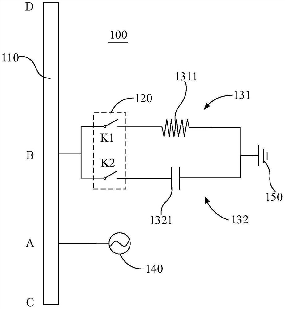
[0032] Optionally, see figure 2 , figure 2 It is a schematic structural diagram of another embodiment of an antenna assembly used in an electronic device of the present application; the antenna assembly 100 in this embodiment also includes but is not limited to a first radiator 110 , a switch 120 , a ground circuit 130 and a first feed source 140 . The first radiator 110 may be a part of the metal frame of an electronic device or an FPC antenna, and the first radiator 110 is provided with a first connection point A and a second connection point B at intervals; the first feed source 140 Connected to the first connection point A, one end of the switch 120 is connected to the second connection point B, and the other end is connected to the ground circuit 130 , and the switch 120 is used to switch the ground circuit 130 The different branches of the first radiator 110 are connected to the second connection point B of the first radiator 110 , so as to switch the radiation mode of the first radiator 110 .
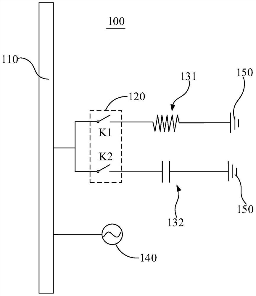
[0033] Optionally, the grounding circuit 130 in this embodiment includes a first branch 131 and a second branch 132, one end of the first branch 131 is connected to the switch 120, and the other end is connected to the ground point 150, One end of the second branch 132 is connected to the switch 120 , and the other end is connected to the grounding point 150 . The first branch 131 and the second branch 132 in this embodiment share the same ground point 150, please refer to image 3 , image 3 is a schematic structural diagram of yet another embodiment of an antenna assembly used in an electronic device of the present application; and figure 2 The difference between the embodiments is that the first branch 131 and the second branch 132 in this embodiment are connected to a ground point 150 respectively.
[0034] Optionally, the switch 120 in this embodiment is two single-pole single-throw switches, please refer to Figure 4 , Figure 4 is a schematic structural diagram of another embodiment of an antenna assembly used in an electronic device of the present application; and figure 2The difference between the embodiments is that the switch 120 in this embodiment is a single-pole double-throw switch. In addition, in some other embodiments, the grounding circuit 130 may also include a plurality of branches, and the switch 120 may be a multi-switch switch structure, which will not be listed and described in detail this time.
[0035] please continue Figure 2 to Figure 4 , the first branch 131 is provided with an inductance device 1311, and the second branch 132 is provided with a capacitive device 1321. Optionally, the inductance device on the first branch 131 is 1-10nH, specifically Can be 1nH, 2nH, 3nH, 5nH, 6nH, 8nH, 10nH and other values. The capacitance device on the second branch 132 is 5-20pF, specifically 5pF, 8pF, 10pF, 12pF, 15pF, 20pF, etc.
[0036] The radiation pattern of the antenna is controlled by controlling the ground return circuit at point B: with figure 2 The middle circuit structure is taken as an example. In mode 1, the switch K1 is closed to make the first branch 131 pass through, and the antenna radiation branch is in the BC segment (C is the end point of the first radiator 110); in mode 2, the switch K2 is closed to make the second branch. The channel 132 is connected, and the antenna radiation branch is in the BD segment (D is the other end of the first radiator 110).
[0037] see Figure 5 , Figure 5 It is a schematic structural diagram of another embodiment of the antenna assembly used for electronic equipment in the present application; the antenna assembly 100 in this embodiment includes but is not limited to a first radiator 110, a switch 120, a ground circuit 130, a first feed 140 and The second feed 160 . The first radiator 110 is provided with a first connection point A, a second connection point B and a third connection point E at intervals; the first feed source 140 is connected to the first connection point A, and the second connection point The feed source 160 is connected to the third connection point E; wherein, the operating frequencies of the second feed source 160 and the first feed source 140 are different, wherein the second feed source 160 may be a low-frequency feed source, and the first feed source 160 The feed source 140 can be a medium and high frequency feed source with a frequency range of 1710MHz-2690MHz.
[0038] One end of the switch 120 is connected to the second connection point B, and the other end is connected to the ground circuit 130. The switch 120 is used to switch different branches of the ground circuit 130 to the second connection point B. The second connection point B of a radiator 110 is connected to switch the radiation mode of the first radiator 110 . The low-frequency radiation branch is the CD segment.
[0039] Optionally, the grounding circuit 130 in this embodiment also includes a first branch 131 and a second branch 132, one end of the first branch 131 is connected to the switch 120, and the other end is connected to the ground point 150 For connection, one end of the second branch 132 is connected to the switch 120 , and the other end is connected to the grounding point 150 . It should be noted that the terms "first", "second" and "third" in the embodiments of the present application are only used for description purposes, and should not be interpreted as indicating or implying relative importance or implicitly indicating the indicated technology number of features. Thus, a feature defined as "first", "second", "third" may expressly or implicitly include at least one of that feature. In the description of the present invention, "a plurality of" means at least two, such as two, three, etc., unless otherwise expressly and specifically defined.
[0040] see Image 6 , Image 6 It is a schematic structural diagram of another embodiment of the antenna assembly used in the electronic device of the present application; different from the previous embodiments, the antenna assembly 100 in this embodiment further includes a second radiator 170, the second radiator 170 and the The first radiators 110 are arranged at intervals, and the second radiators 170 and the first radiators 110 together enclose a radiation unit forming a rectangular ring structure, and the first radiators 110 are located in the rectangular ring structure on the long side of the radiating element. A fourth connection point G is provided on the second radiator 170 , and the fourth connection point G is connected to the ground point 150 . The high-frequency radiation branch is the FG segment (F is the end point of the second radiator 170). In order to prevent the mid-frequency radiation branches from being held when the electronic device is held horizontally, the radiation branches will be in the CB segment, but the CB segment will be held in the one-handed state. In order to improve this situation, this scheme uses The IF can work in two different radiation modes, mode 1, the radiation branch is in the CB segment, mode 2, the radiation branch is in the BD segment. It is guaranteed that it will not be grasped in both usage scenarios.
[0041] Please also refer to Figures 7a to 7c , Figure 7a is the comparison diagram of the radiation efficiency of the free-space antenna under the working state of the antenna assembly in mode 1 and mode 2, Figure 7b It is the comparison chart of the antenna radiation efficiency of mode 1 and mode 2 when the electronic device is in the horizontal screen holding state. Figure 7c It is a comparison diagram of the antenna radiation efficiency of mode 1 and mode 2 when the electronic device is held in one hand. LTE (Long Term Evolution, long term evolution technology) B3 (frequency range 1710MHz-1880MHz) is the most used frequency band for the intermediate frequency band, and here we focus on comparing B3. Please refer to the table below in combination.
[0042]
[0043] It can be seen that the efficiency of the two modes is similar in free space. The horizontal screen holding mode 1 is 4dB higher than the mode 2, and the one-hand holding mode 2 is 6dB higher than the mode 1. That is, the design of this solution not only ensures the performance of the antenna when the game is held in a horizontal screen, but also greatly improves the performance of the antenna when it is held by one hand.
[0044] The technical solution in this embodiment ensures the antenna performance when the mobile phone is held in the horizontal screen by designing the antenna on the side of the mobile phone. Different from the existing game antenna design, this solution adds a switch so that the LTE MB (intermediate frequency) can be Two radiation modes are generated. Since the radiation branches of the two modes are different, it can be ensured that the antenna will not be grasped when the horizontal screen is held by hand or when held by one hand, so that the two use scenarios are taken into account.
[0045] The solution in the embodiment of the present application is essentially a reconfigurable multi-mode antenna, which is not limited to the game antenna on the side. Antennas at other positions can also be designed to generate different modes and be applied to different scenarios. In addition, it can also be made not limited to the LTE MB band by adding costs such as switches.
[0046] Further, the embodiment of the present application also provides an electronic device, please refer to Figure 8 , Figure 8 It is a schematic partial structure diagram of an embodiment of the electronic device of the present application. The electronic device 10 in this embodiment includes a processor 200, a radio frequency transceiver module 300, and an antenna assembly 100. For the detailed structure of the antenna assembly 100, please refer to the related aspects of the foregoing embodiments. description, which will not be described in detail here.
[0047] The processor 200 is connected to the switch 120 of the antenna assembly 100 for controlling the switch 120 to switch between different branches of the ground circuit 130 and the second connection point of the first radiator 110 connection, so as to switch the radiation mode of the first radiator 110 . The radio frequency transceiver module 300 is electrically connected to the first radiator 110 and the processor 200 respectively. The radio frequency transceiver module 300 is controlled by the processor 200 and is used for transmitting and receiving radio frequency signals through the first radiator 110 . It should be noted that all directional indications (such as up, down, left, right, front, back...) in the embodiments of the present application are only used to explain the relationship between the various components under a certain posture (as shown in the drawings). If the specific posture changes, the directional indication also changes accordingly.
[0048] see Figure 9 , Figure 9 This is a schematic block diagram of the structure and composition of an embodiment of an electronic device of the present application. The electronic device may be a mobile phone, a tablet computer, a notebook computer, a wearable device, and the like. The illustration in this embodiment takes a mobile phone as an example. The structure of the electronic device 10 may include an RF circuit 910 (which may be the antenna assembly 100 in the foregoing embodiment), a memory 920, an input unit 930, a display unit 940, a sensor 950, an audio circuit 960, a wifi module 970, a processor 980 ( It can be the processor 200) and the power supply 990 in the foregoing embodiments. The RF circuit 910 , the memory 920 , the input unit 930 , the display unit 940 , the sensor 950 , the audio circuit 960 and the wifi module 970 are respectively connected to the processor 980 ;
[0049] Specifically, the RF circuit 910 is used to send and receive signals; the memory 920 is used to store data instruction information; the input unit 930 is used to input information, which may specifically include a touch panel 931 and other input devices 932 such as operation keys; the display unit 940 is used for The sensor 950 may include a display panel 941, etc.; the sensor 950 includes an infrared sensor, a laser sensor, etc., for detecting user proximity signals, distance signals, etc.; the speaker 961 and the microphone (or microphone) 962 are connected to the processor 980 through the audio circuit 960, for connecting The wifi module 970 is used to receive and transmit wifi signals, and the processor 980 is used to process the data information of the electronic device. For specific structural features of the electronic device, please refer to the relevant descriptions of the above-mentioned embodiments, which will not be described in detail here.
[0050] In the electronic device in this embodiment, by setting the switch in the antenna component, the same radiator can generate two radiation modes. Since the radiation branches of the two modes are different, it can be ensured that the antenna can be held in both the horizontal screen and the one-handed hand. It will not be grasped, and it can take into account the two usage scenarios and improve the radiation performance of the antenna.
[0051] In addition, an embodiment of the present application also provides a control method for an electronic device, please refer to Figure 10 , Figure 10 This is a schematic flowchart of an embodiment of an electronic device control method of the present application, and the control method includes but is not limited to the following steps.
[0052] Step S100, detecting the use state of the electronic device.
[0053] In this step, the gravity sensor in the electronic device may be used to detect whether the electronic device is in a horizontal screen state or a vertical screen state.
[0054] Step S200, controlling the antenna assembly to switch to a corresponding radiation mode according to the use state of the electronic device.
[0055] In this step, it is specifically realized by controlling the switch in the antenna assembly.
[0056] Please also refer to Figure 11 , Figure 11 It is a schematic flowchart of a specific embodiment of the electronic device control method of the present application, and the control method includes but is not limited to the following steps.
[0057] Step S201, detecting the screen state of the electronic device.
[0058] In step S201, it may be specifically implemented by a gravity sensor in an electronic device.
[0059] Step S202, it is determined whether the electronic device is in a horizontal screen state or a vertical screen state.
[0060] In this step, if the electronic device is in the horizontal screen state, go to step S203 to control the antenna assembly to switch to the first mode; if the electronic device is in the vertical screen state, go to step S204 to control the antenna assembly to switch to the second mode. For the specific working states of the first mode and the second mode, please refer to the foregoing description about the embodiments of the antenna assembly.
[0061] The electronic device control method in the embodiment of the present application can improve the antenna performance of the electronic device in different working modes by detecting the use state of the electronic device and control the antenna assembly to switch to the corresponding radiation mode, thereby improving the user experience of the electronic device.
[0062] The above descriptions are only some embodiments of the present invention, and are not intended to limit the protection scope of the present invention. Any equivalent device or equivalent process transformation made by using the contents of the description and drawings of the present invention, or directly or indirectly applied to other related All technical fields are similarly included in the scope of patent protection of the present invention.

PUM

no PUM

Description & Claims & Application Information

We can also present the details of the Description, Claims and Application information to help users get a comprehensive understanding of the technical details of the patent, such as background art, summary of invention, brief description of drawings, description of embodiments, and other original content. On the other hand, users can also determine the specific scope of protection of the technology through the list of claims; as well as understand the changes in the life cycle of the technology with the presentation of the patent timeline. Login to view more.

Similar technology patents

Handheld communication device with coupled slot antenna module

InactiveCN102290636AImprove return lossImprove Radiation PerformanceAntenna supports/mountingsRadiating elements structural formsPhysicsRF module
Owner:ACCTON TECHNOLOGY CORPORATION

Antenna

Owner:东莞市森岭智能科技有限公司

Radiating element for antenna and antenna comprising same

PendingCN112864604AAccurate realizationImprove Radiation PerformanceSimultaneous aerial operationsRadiating elements structural formsDipoleRadiation
Owner:PROSE TECH CO LTD

An antenna oscillator for a base station

PendingCN109244652AImprove Radiation PerformanceIncreased cross-polarization ratioRadiating elements structural formsAntennas earthing switches associationFeed lineCross polarization
Owner:深圳市鑫龙通信技术有限公司

AFU antenna

PendingCN114122702AImprove Radiation PerformanceAvoid Poor Antenna Performance StabilityRadiating elements structural formsRadiating element housingsRadomeBase station antennas
Owner:WUHAN HONGXIN TELECOMM TECH CO LTD

Classification and recommendation of technical efficacy words

  • Improve Radiation Performance

Rotating Electrical Machine

Owner:HITACHI ASTEMO LTD

Display Device

Owner:PANASONIC CORP

Metal frame mobile phone antenna

Owner:SHANGHAI AMPHENOL AIRWAVE COMM ELECTRONICS
Why Eureka
Try Eureka