
Direct-current valve hall wall bushing structure

A technology of wall-piercing bushings and DC valves, which is applied in the direction of gas-filled/oil-filled cable fittings, cable joints, electrical components, etc., which can solve problems such as difficulty in bearing excessive loads, and achieve fatigue damage avoidance, strong bearing capacity, Effect of Avoiding Overheating Defects

Pending Publication Date: 2022-07-29
EXAMING & EXPERIMENTAL CENT OF ULTRAHIGH VOLTAGE POWER TRANSMISSION COMPANY CHINA SOUTHEN POWER GRID
View PDF0 Cites 0 Cited by
  • Summary
  • Abstract
  • Description
  • Claims
  • Application Information

AI Technical Summary

Problems solved by technology

[0004] Based on this, it is necessary to provide a DC valve hall wall bushing structure for the problem that the wall bushing of the converter station in the high altitude / high seismic intensity area is difficult to withstand excessive loads

Method used


Image

  • Direct-current valve hall wall bushing structure
  • Direct-current valve hall wall bushing structure
  • Direct-current valve hall wall bushing structure

Examples


Embodiment Construction

[0028] In order to make the above objects, features and advantages of the present invention more clearly understood, the specific embodiments of the present invention will be described in detail below with reference to the accompanying drawings. In the following description, numerous specific details are set forth in order to provide a thorough understanding of the present invention. However, the present invention can be implemented in many other ways different from those described herein, and those skilled in the art can make similar improvements without departing from the connotation of the present invention. Therefore, the present invention is not limited by the specific embodiments disclosed below.

[0029] In the description of the present invention, it should be understood that the terms "center", "longitudinal", "lateral", "length", "width", "thickness", "upper", "lower", "front", " Back, Left, Right, Vertical, Horizontal, Top, Bottom, Inner, Outer, Clockwise, Countercl...


PUM


Abstract

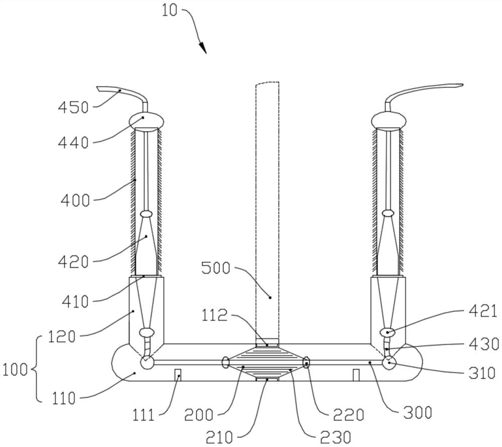
The invention relates to a direct-current valve hall wall bushing structure which comprises a wall bushing, an insulating support, a current-carrying conductor and a wire outlet bushing, the wall bushing comprises a pipeline shell and wire outlet ascending flangings vertically and fixedly connected to the two sides of the pipeline shell, the wire outlet ascending flangings are communicated with the pipeline shell, the pipeline shell is fixedly connected with a foundation, and the insulating support is fixedly connected with the wire outlet ascending flangings. The pipeline shell penetrates through the valve hall wall and is elastically and fixedly connected to the bottom of the valve hall wall. The insulating support is fixedly connected to the interior of the pipeline shell; the current-carrying conductor is arranged in the pipeline shell, and the current-carrying conductor penetrates through the insulating support and is in sliding connection with the insulating support; and a wire outlet sleeve is coaxially and fixedly connected to the wire outlet ascending flanged base, and an overhead line in the wire outlet sleeve is electrically connected with the current-carrying conductor. After the pipeline shell is vertically and fixedly connected with the outgoing line ascending flanged base, the weight of the outgoing line sleeve and the weight of a laid line of the outgoing line sleeve can be diffused in the vertical direction, and the situation that the through-wall pipeline is fatigued and damaged is avoided.

Description

technical field [0001] The invention relates to the technical field of wall bushings, in particular to a wall bushing structure of a direct current valve hall. Background technique [0002] With the development of HVDC transmission technology, DC transmission has played a huge role in the composition of China's power grid, and through-wall bushings are one of the main power equipment in HVDC converter stations. For converter stations in high-altitude / high-earthquake-intensity areas, the electrical equipment considers the reliability of the external insulation at high altitude and low pressure, so altitude correction needs to be carried out to increase the length of the external insulation; electrical equipment considers the mechanical strength under high seismic intensity, and the structural design needs to be optimized , Select the material, and enhance the mechanical reliability of the equipment by means of strengthening and thickening. The DC through-wall bushing is insta...

Claims


Application Information

Patent Timeline
Patent Type & Authority Applications(China)
IPC IPC(8): H02G3/22H02G15/20H02G15/18
CPCH02G3/263H02G15/20H02G15/18
Inventor 张晋寅杨旭邓军韦晓星潘志城谢志成
Owner EXAMING & EXPERIMENTAL CENT OF ULTRAHIGH VOLTAGE POWER TRANSMISSION COMPANY CHINA SOUTHEN POWER GRID
Learn More