Surge current suppression circuit

A current suppression and circuit technology, applied in circuit devices, emergency protection circuit devices for limiting overcurrent/overvoltage, emergency protection circuit devices, etc. And other problems, to achieve the effect of suppressing the inrush current and improving the safety of the circuit

Pending Publication Date: 2022-07-29
致茂电子(苏州)有限公司
View PDF0 Cites 0 Cited by
  • Summary
  • Abstract
  • Description
  • Claims
  • Application Information

AI Technical Summary

Problems solved by technology

Although the damage of the switch can be avoided, it still cannot suppress the inrush current from flowing to the internal circuit of the electronic device, causing the instantaneous current required by the internal circuit of the electronic device to rise, causing the fuse to blow or the circuit breaker to open, thereby affecting the circuit safety
In other words, the existing current suppression circuit can only suppress the inrush current generated by the initial input power signal when the electronic device is started, but cannot suppress the inrush current generated by the abnormal input power signal after the electronic device is started.
[0004] Therefore, in order to improve the circuit safety of electronic devices when the initial input power signal is input and when the input power signal is abnormal, the current current suppression technology still needs to be improved

Method used


Image

  • Surge current suppression circuit
  • Surge current suppression circuit
  • Surge current suppression circuit

Examples


Embodiment Construction

[0054] In order to fully understand the purpose, features and effects of the present invention, the present invention will now be described in detail through the following specific embodiments and in conjunction with the accompanying drawings, as follows.

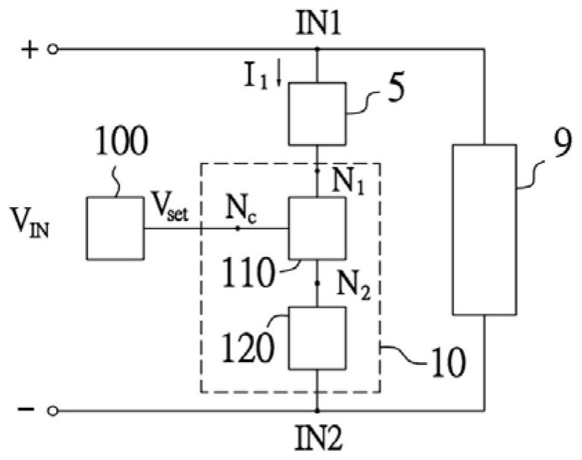
[0055] Please refer to figure 1 , which is a schematic block diagram of an application scenario of an embodiment of the surge current suppression circuit. like figure 1 As shown, the inrush current suppressing circuit 10 can be applied to an electronic device to suppress the current magnitude of the input capacitor (eg, the capacitive device 5 ) of the electronic device. For example, the electronic device is, for example, a power conversion device, an electronic testing device, or other devices, and has a first power input terminal IN1 and a second power input terminal IN2 to receive the input power signal VIN, and includes a capacitive device 5 and an internal circuit 9. The internal circuit 9 is a post-stage circuit or...


PUM


Abstract

A surge current suppression circuit is used for being connected in series with a capacitive device and coupled with the capacitive device between a first power supply input end and a second power supply input end, and comprises an active switch unit and a current detection unit. The active switch unit is connected in series with the capacitive device and has a control terminal for receiving a control voltage signal. The current detection unit is connected in series with the active switch unit and is used for generating a detection voltage signal according to the flowing first current. When a first current flows in from the first power supply input end and passes through the current detection unit, the current detection unit generates a detection voltage signal, and when the detection voltage signal is greater than or equal to a detection voltage threshold value, the active switch unit is closed, thereby suppressing the first current.

Description

technical field [0001] The invention relates to a protection circuit, in particular to a surge current suppression circuit. Background technique [0002] For the internal circuit of the electronic device, in order to suppress the input inrush current, a current suppression circuit is usually provided at the input end of the electronic device. Existing current suppression circuits, for example, include a resistor and a switch such as a relay connected in parallel with the resistor. When the electronic device is turned on, the inrush current generated by the input power signal is limited by the resistance of the current suppression circuit. When the current suppression circuit enters a steady state, the switch of the current suppression circuit will be turned on, so that the input power signal enters the internal circuit (or system load) of the electronic device through the switch to reduce losses. [0003] However, after the electronic device is turned on, when the source o...

Claims


Application Information

Patent Timeline
Patent Type & Authority Applications(China)
IPC IPC(8): H02H9/04H02H9/02
CPCH02H9/04H02H9/025
Inventor 吴健铭吴冠宏陈柏豪
Owner 致茂电子(苏州)有限公司
Why Eureka
Try Eureka