
Single-phase immersed liquid cooling cabinet

An immersion and liquid cooling technology, applied in the direction of cooling/ventilation/heating transformation, etc., can solve the problems of poor heat dissipation effect of liquid cooling and large flow of coolant

Pending Publication Date: 2022-07-29
SHENZHEN MICROBT ELECTRONICS TECH CO LTD
View PDF0 Cites 0 Cited by
  • Summary
  • Abstract
  • Description
  • Claims
  • Application Information

AI Technical Summary

Problems solved by technology

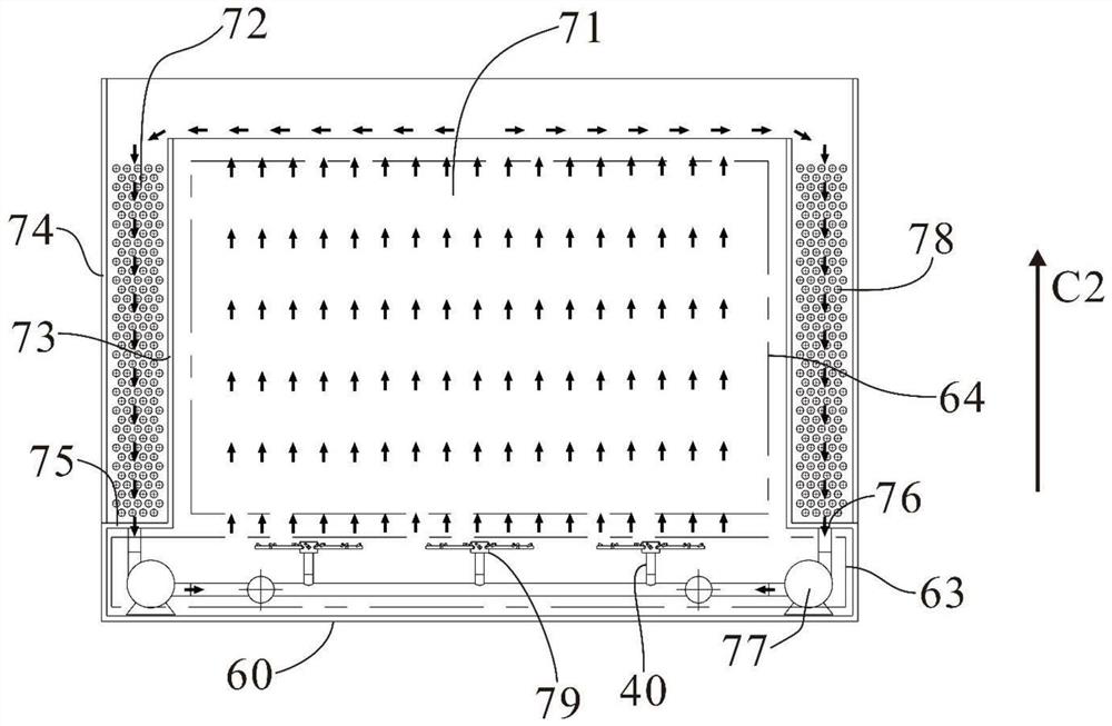
[0007] That is, in the embodiment of the present application, during the circulation of the cooling liquid, on the one hand, the cooling liquid overflows from the first accommodating space to the second accommodating space, and the flow rate of the cooling liquid is relatively large; Correspondingly, the two accommodating spaces are connected through a power drive device; that is to say, in the embodiment of the present application, the external cold source is built into the liquid-cooled cabinet, and the two accommodating spaces are double-layered, and one end overflows the other end The setting of China Unicom solves the technical problem of poor liquid cooling and heat dissipation effect caused by the limited system design when the coolant passes through the pipeline to an external cold source; through the above settings, the circulation flow rate of the coolant is increased, and the cooling capacity of the coolant is improved. Convective heat transfer performance, thereby improving the liquid cooling effect of the coolant on electronic equipment

Method used


Image

  • Single-phase immersed liquid cooling cabinet
  • Single-phase immersed liquid cooling cabinet
  • Single-phase immersed liquid cooling cabinet

Examples


Embodiment Construction

[0058] In order to better understand the above technical solutions, the exemplary embodiments of the present application will be described in detail below with reference to the accompanying drawings. Obviously, the described embodiments are only a part of the embodiments of the present application, not all the embodiments of the present application. It is understood that the present application is not limited by the exemplary embodiments described herein.

[0059] Submerged liquid-cooled cabinets dissipate heat from electronic equipment through circulating coolant.

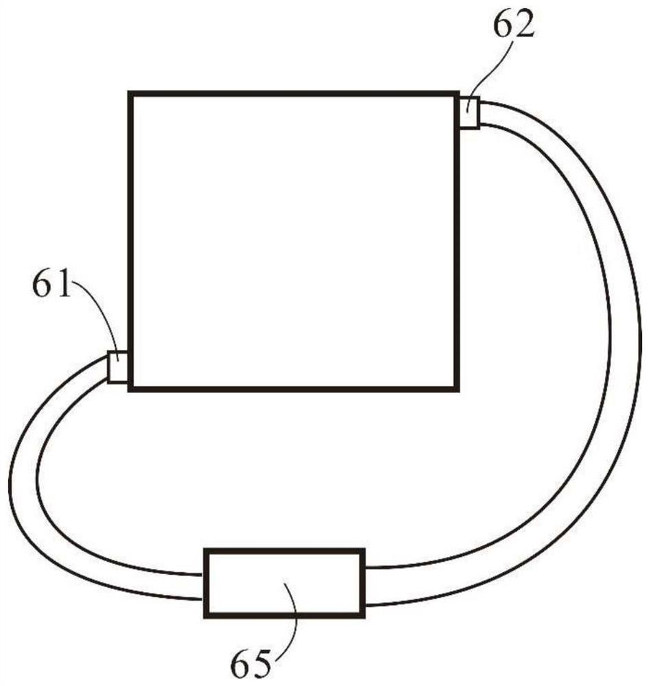
[0060] Common submerged liquid cooling cabinets are designed as a container with an upper opening and a certain volume, see figure 1 , multiple electronic devices can be installed in it, and it is filled with insulating cooling liquid. The liquid cooling cabinet is provided with a cooling liquid inlet 61 at the bottom and a cooling liquid outlet 62 at the top. The low-temperature cooling liquid exchanges heat with...


PUM


Abstract

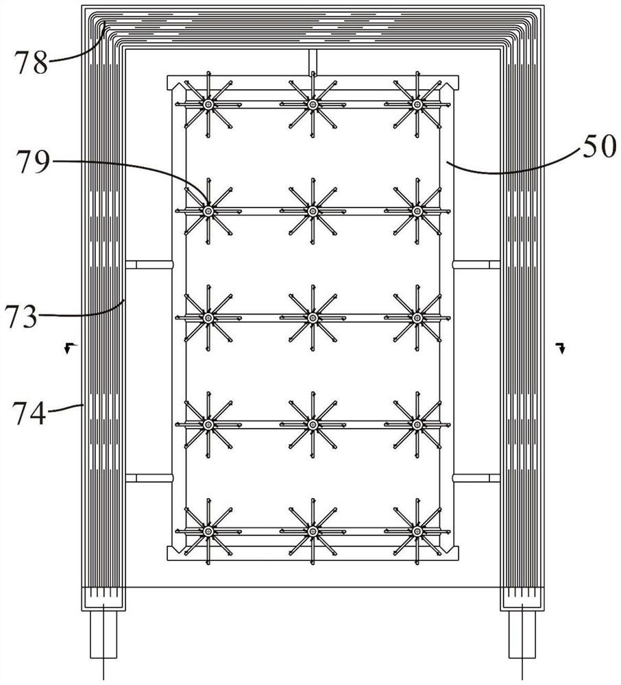
The invention discloses a single-phase immersed liquid-cooled cabinet, the liquid-cooled cabinet comprises a first shell and a second shell, the first shell forms a first accommodating space, one end of the first accommodating space along a second direction is provided with a power driving device, and then the first accommodating space is provided with a power driving device on the circumferential outer side of the first shell along the second direction. A first accommodating space is formed between the first shell and the second shell, a second accommodating space is formed between the second shell and the first shell, the first accommodating space is used for bearing electronic equipment, and the second accommodating space is used for bearing a heat exchanger device; the two accommodating spaces are respectively communicated through the power driving device at one end and the opening at the other end; in this way, the cooling liquid circularly flows between the two accommodating spaces, so that liquid cooling heat dissipation can be carried out on the electronic equipment in the first accommodating space; therefore, the technical problem that the liquid cooling heat dissipation effect is poor when the cooling liquid is externally connected with a cold source through a pipeline is solved.

Description

technical field [0001] The invention relates to the technical field of liquid cooling and heat dissipation, in particular to a single-phase submerged liquid cooling cabinet. Background technique [0002] Submerged liquid-cooled cabinets dissipate heat from electronic equipment through circulating coolant. [0003] The lower end of the liquid cooling cabinet is provided with a cooling liquid inlet, and the upper end is provided with a cooling liquid outlet, and the electronic equipment is placed inside the liquid cooling cabinet. After the heat is generated, it flows out from the outlet at the upper end, and then exchanges heat with the external cold source through the pipeline. After cooling, it flows in from the inlet of the liquid cooling cabinet, and thus circulates, so as to carry out liquid cooling and heat dissipation for the electronic equipment. [0004] However, as mentioned above in the prior art, the inlet and outlet of the liquid-cooling cabinet and the cooling ...

Claims


Application Information

Patent Timeline
IPC IPC(8): H05K7/20
CPCH05K7/20272H05K7/20236
Inventor 陈前刘方宇巫跃凤高阳宁洪燕
Owner SHENZHEN MICROBT ELECTRONICS TECH CO LTD
Learn More