
Cargo loading and unloading equipment for railway vehicle

A technology for loading and unloading of goods, railway vehicles, applied in the direction of railway transportation, railway transportation, loading/unloading, etc.

Pending Publication Date: 2022-08-02
HUNAN VOCATIONAL COLLEGE OF RAILWAY TECH
View PDF0 Cites 0 Cited by
  • Summary
  • Abstract
  • Description
  • Claims
  • Application Information

AI Technical Summary

Problems solved by technology

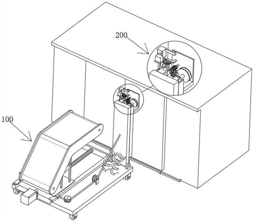
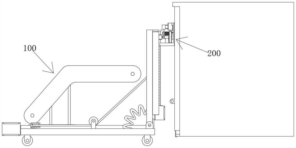
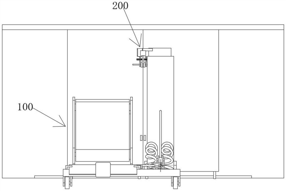
[0005] In order to overcome the above-mentioned technical problems, the object of the present invention is to provide a kind of cargo handling equipment for railway vehicles. A loading and unloading mechanism is provided in the cargo handling equipment for railway vehicles, and the servo motor in the loading and unloading mechanism can drive the screw to rotate. , so that the moving block can be driven to move on the moving base, and the conveying platform can be driven to move, so that the conveying platform can extend into the interior of the railway box car, which is convenient for loading and unloading of goods through the conveying platform, and when the moving block is moving, it can pass through The connecting block on one side can pull the connecting rope to slide on the positioning wheel, thereby driving the rotating plate to rotate between the two positioning seats, so that the welding mechanism on the rotating plate can be rotated and stored to prevent interference with the loading and unloading of goods , when the cargo loading and unloading is completed, by driving the moving block and the conveying platform to translate back, the rotating plate can be rotated under the extrusion of two extrusion springs, so that the rotating plate is in an upright state under the limit of the baffle, so that It can make the rotating plate parallel to the door of the box car, which is convenient to use the welding mechanism to weld the door nose on the door of the box car, so that the loading and unloading equipment can quickly strengthen and seal the door of the box car after loading and unloading the goods; through the rotating plate The servo motor 2 can drive the screw rod 2 to rotate, which can drive the lifting table to move up and down in the vertical direction, so that it is convenient to penetrate the steel wire and then bend the door nose at different positions on the boxcar door for welding The driving motor in the welding mechanism can drive the rotating shaft, so that the steel wire disc can be driven to rotate through the sliding cylinder, so that the steel wire can be output from the wire outlet pipe, so that the steel wire can pass through the doors on both sides. When the shaft rotates, the belt and pulley 1 can be driven to rotate through the pulley 2, thereby driving the worm to rotate, because the worm needs to rotate multiple turns to drive the worm wheel to rotate once, so as the steel wire After stretching out for a certain distance, the worm wheel can drive the rotating shaft 2 to rotate one circle, so that the wire cutter can cut the steel wire, and then the servo motor 3 can drive the two gears to mesh and rotate, so as to pass through the two bends at the bottom The seat bends the steel wire that passes through the door nose. When the two ends of the steel wire are bent to touch each other, the steel wire can be welded by a spot welder. This can strengthen the connection of the doors on both sides and prevent the door locks on both sides. After the buckle falls off, the steel wires welded on the nose of multiple places can prevent the door from sliding, which will lead to accidental side leakage of the goods inside the box car when the door is opened.

Method used


Image

  • Cargo loading and unloading equipment for railway vehicle
  • Cargo loading and unloading equipment for railway vehicle
  • Cargo loading and unloading equipment for railway vehicle

Examples


Embodiment Construction

[0029] The technical solutions in the embodiments of the present invention will be clearly and completely described below with reference to the embodiments of the present invention. Obviously, the described embodiments are only a part of the embodiments of the present invention, rather than all the embodiments. Based on the embodiments of the present invention, all other embodiments obtained by those of ordinary skill in the art without creative efforts shall fall within the protection scope of the present invention.

[0030] see Figure 1-8 As shown, a cargo loading and unloading equipment for railway vehicles includes a loading and unloading mechanism 100, and a welding mechanism 200 is fixedly arranged on the top of the loading and unloading mechanism 100;

[0031] The welding mechanism 200 includes a lifting table 201. A driving motor 203 is fixedly connected to the top of the lifting table 201. A rotating shaft 204 is fixedly connected to the output end of the driving mot...


PUM


Abstract

The invention relates to the technical field of loading and unloading equipment, in particular to cargo loading and unloading equipment for railway vehicles, which comprises a loading and unloading mechanism, and a welding mechanism is fixedly arranged at the top of the loading and unloading mechanism. According to the loading and unloading device for the railway box car, a first servo motor in the loading and unloading mechanism can drive a first screw rod to rotate, so that a moving block can be driven to move on a moving base, a conveying platform can be driven to move, the conveying platform can stretch into the railway box car, and goods can be conveniently loaded, unloaded and transported through the conveying platform; the moving block and the conveying platform are driven to translate back and forth, and the rotating plate can rotate under the extrusion of the two extrusion springs, so that the rotating plate is in an upright state under the limiting of the baffle plate, the rotating plate can be parallel to the car door of the railway box car, and a welding mechanism is conveniently utilized to perform steel wire welding on the door knob on the car door of the railway box car; therefore, loading and unloading equipment can conveniently and quickly reinforce and seal the boxcar door after loading and unloading goods.

Description

technical field [0001] The invention relates to the technical field of loading and unloading equipment, in particular to a cargo loading and unloading equipment for railway vehicles. Background technique [0002] Rail freight transportation is a form of transportation that uses railway trains to transport goods. It plays an important role in the social material production process. It is characterized by large transportation volume, fast speed and low cost, generally not restricted by climatic conditions, and suitable for long-distance transportation of bulk and heavy goods. [0003] As an important means of transportation in railway transportation, boxcar is characterized in that the upper part of the car is provided with a roof that can protect from sun and rain, and the middle of the car is open on both sides, which is mainly used to transport some goods that are susceptible to moisture or cannot be exposed to sunlight. Boxcars have better protection when transporting sp...

Claims


Application Information

Patent Timeline
IPC IPC(8): B65G69/00B65G67/10
CPCB65G69/00B65G67/10Y02T30/00
Inventor 陈芳
Owner HUNAN VOCATIONAL COLLEGE OF RAILWAY TECH
Learn More