Shear wall structure and method
A shear wall and connection structure technology, which is applied in the construction of shear wall structures and in the field of shear wall structures, can solve problems such as water seepage and straight seam joint leakage, and achieve the effect of reliable connection and simple connection process
- Summary
- Abstract
- Description
- Claims
- Application Information
AI Technical Summary
Problems solved by technology
Method used
Image

Examples
Embodiment 1
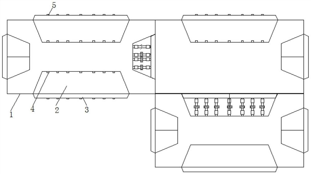
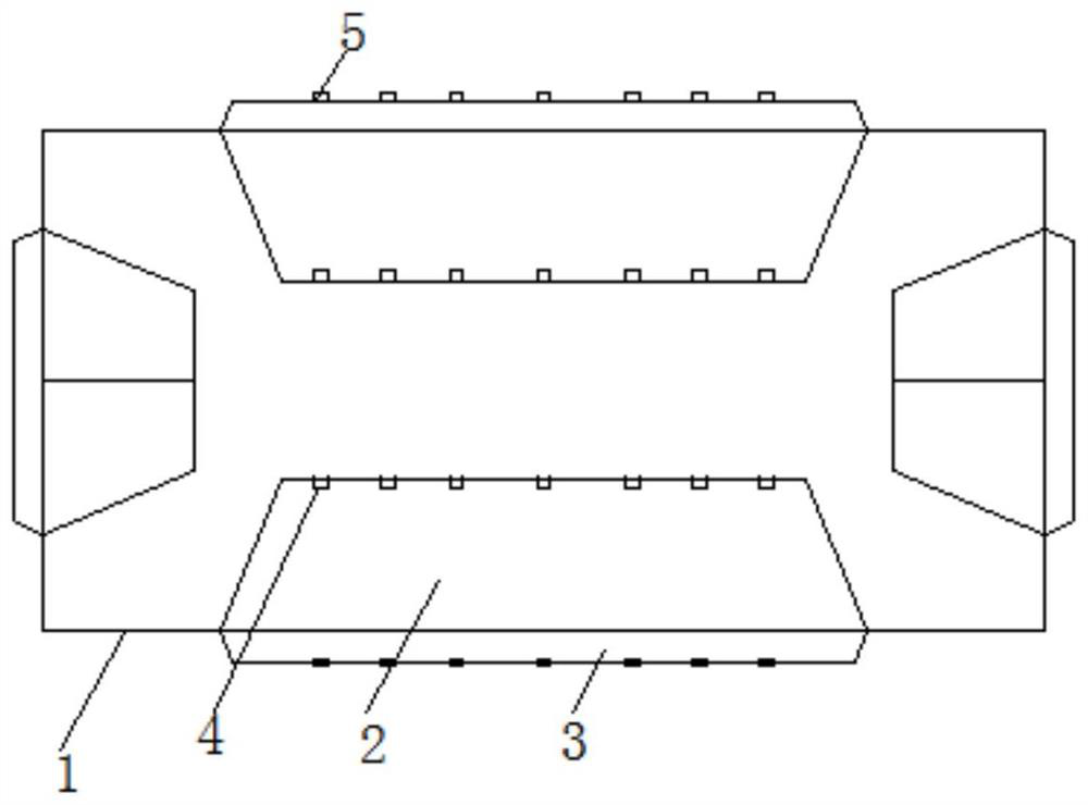
[0033] A shear wall structure of the present invention, such as Figure 1-2 As shown, it includes: a prefabricated wall panel 1 and a steel bar connection structure, wherein the upper and lower end faces and the left and right sides of the prefabricated wall panel 1 are alternately provided with wedge-shaped grooves 2 and wedge-shaped connecting blocks 3, wedge-shaped grooves 2 and wedge-shaped connecting blocks 3 Arranged in turn along the thickness direction of the prefabricated wall panels 1, each wedge-shaped groove 2 is also provided with a plurality of first connecting steel bars 4, and the wedge-shaped connecting block 3 is also provided with a second connecting steel bar 5 on the connecting block; It is used to connect the first steel bar 4 and the second connecting steel bar 5 of two prefabricated wall panels 1 adjacent to each other in the lateral and vertical directions of the prefabricated wall panel 1 .
Embodiment 2
[0035] Further, on the basis of Embodiment 1, for the convenience of connection, one wedge-shaped groove 2 and one wedge-shaped connecting block 3 are provided on each surface of the prefabricated wall panel. The wedge-shaped groove 2 on the upper end surface of each prefabricated wall panel 1 is correspondingly arranged with the wedge-shaped connecting block 3 on the lower end surface, and the wedge-shaped connecting block 3 on the upper end surface is correspondingly arranged with the wedge-shaped groove 2 on the lower end surface. The wedge-shaped groove 2 on the left side of each prefabricated wall panel 1 is arranged corresponding to the wedge-shaped connecting block 3 on the right side, and the wedge-shaped connecting block 3 on the left side is correspondingly arranged with the wedge-shaped groove 2 on the right side. Therefore, when connecting, the wedge-shaped groove 2 on the adjacent two prefabricated wall panels 1 is connected with the wedge-shaped connecting block 3...
Embodiment 3
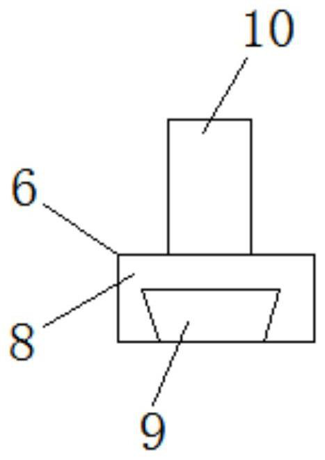
[0037] On the basis of Example 2, further, such as Figure 3-5 As shown, the reinforcing bar connection structure includes a first connection structure 6 and a second connection mechanism 7, one end of the first connection structure 6 is a rectangular block 8, one side of the rectangular block 8 is provided with an inverted T-shaped groove 9, and the rectangular block 8 is away from The other end face of the inverted T-shaped groove 9 is provided with a first steel bar 10 with an external thread. It is a second reinforcing bar 12 with an external thread, wherein the first reinforcing bar 10 is connected with the second connecting bar 5 in the adjacent wall panel through a sleeve, and the second reinforcing bar 12 is connected with the first connecting bar 4 in the adjacent wall panel Connected by socket.
[0038] Further, the depth of the wedge-shaped groove 2 is the same as the sum of the heights of the wedge-shaped connecting block 3 , the second connecting steel bar 5 , th...
PUM
 Abstract
Description
Claims
Application Information
 - R&D
- Intellectual Property
- Life Sciences
- Materials
- Tech Scout
- Unparalleled Data Quality
- Higher Quality Content
- 60% Fewer Hallucinations
Browse by: Latest US Patents, China's latest patents, Technical Efficacy Thesaurus, Application Domain, Technology Topic, Popular Technical Reports.
© 2025 PatSnap. All rights reserved.Legal|Privacy policy|Modern Slavery Act Transparency Statement|Sitemap|About US| Contact US: help@patsnap.com