
Multifunctional replacing-type blasting electrode for plasma blasting experimental system

An experimental system and plasma technology, applied in the field of multifunctional replacement blasting electrodes, can solve the problems of low success rate, complicated operation process, scrapping of blasting electrodes, etc., and achieve the effects of simple manufacturing and processing, simple connection process, and reduced experimental cost.

Inactive Publication Date: 2019-06-07
NORTHEASTERN UNIV
View PDF6 Cites 0 Cited by
  • Summary
  • Abstract
  • Description
  • Claims
  • Application Information

AI Technical Summary

Problems solved by technology

[0006] ①, the size of the blasting electrode is large
[0007] Since the plasma blasting experimental system uses the instantaneous release of high-voltage electric energy to generate an explosion, the insulation effect between the positive and negative electrodes needs to be very reliable at the blasting electrode where the explosion energy is released, otherwise "creeping" will occur during the plasma blasting process. "phenomenon, and cause the explosion energy to be unable to be released concentratedly at the metal wire at the end of the electrode, thus affecting the blasting effect; and in the plasma blasting experimental system, the currently used blasting electrode adopts the "center-circle" electrode arrangement In this way, the center of the blasting electrode is a copper rod with a diameter of 3 mm, and the outer surface of the copper rod is wrapped with a polyethylene insulating layer with a thickness of 4 mm, and a copper tube with a wall thickness of 2.5 mm is placed outside the polyethylene insulating layer. At this time, the overall diameter of the blasting electrode is It reached 16mm; when carrying out the blasting experiment, it is necessary to put the blasting electrode into the drilled hole of the rock and other brittle material specimens, so the diameter of the drilled hole should be at least 17mm; The size of the specimen should also increase accordingly, otherwise the geometric similarity parameters in the physical similarity experiment cannot be met, and the increase in the size of the specimen puts forward higher requirements for other related equipment in the experiment
[0008] ②. The preparation process of blasting electrodes is complex
[0009] During the plasma blasting experiment, it is necessary to coil a certain length of metal wire into a mosquito-repellent coil shape, and then fix the two ends of the wire to the positive and negative poles of the blasting electrode respectively with solder; the central copper rod of the currently used blasting electrode is the positive pole, There is a small hole at one end of the positive copper rod, and the external copper tube is the negative pole. When installing the metal wire, first insert one end of the metal wire into the small hole of the positive copper rod, and then connect the metal wire and the positive copper rod together by soldering , and then coil the metal wire into the desired shape, and finally solder the other end of the wire to the surface of the negative copper tube, but it is very easy to touch the insulating layer between the positive and negative electrodes during the soldering process, resulting in insulation failure, and at the same time Due to the large volume and smooth surface of the negative copper tube, it takes a long time to heat the metal wire and the negative copper tube together, which makes the whole operation process complicated and the success rate is very low
[0010] ③. Low reuse rate of blasting electrodes
[0011] In the plasma blasting experimental system, the blasting electrode should have the ability to be reused many times. After each blasting, it is only necessary to reinstall the metal wire between the positive and negative electrodes; however, in actual use, each blasting will Cause certain damage to the insulating layer between the positive and negative electrodes, or cause local melting and deformation of the insulating layer during the welding wire process, and once the insulating layer has a weak part, the insulating layer is easily broken down when the electrode discharges In this case, the insulation layer can only be replaced; when the situation is serious, it may also cause deformation and damage to the positive copper rod in the center of the blasting electrode, which will lead to the scrapping of the entire blasting electrode; therefore, the currently used blasting electrode The reuse rate is low, and the production cost of the blasting electrode is high, which makes the material consumption and cost of the plasma blasting experiment high
[0012] ④, single blasting electrode function
[0013] In blasting engineering, blasting is mainly carried out with columnar charges (the length of the charge coil is much larger than the diameter of the charge roll), while the metal wires of the blasting electrodes currently used are arranged in the form of coil wires. When performing blasting experiments, only spherical charges can be simulated. The explosion of the charge pack (the ratio of the length of the charge roll to the diameter of the charge roll is less than 3) in the borehole restricts the development of research to a certain extent

Method used


Image

  • Multifunctional replacing-type blasting electrode for plasma blasting experimental system
  • Multifunctional replacing-type blasting electrode for plasma blasting experimental system
  • Multifunctional replacing-type blasting electrode for plasma blasting experimental system

Examples


Embodiment Construction

[0032] The present invention will be further described in detail below in conjunction with the accompanying drawings and specific embodiments.

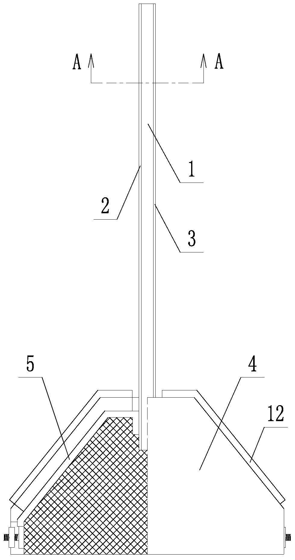
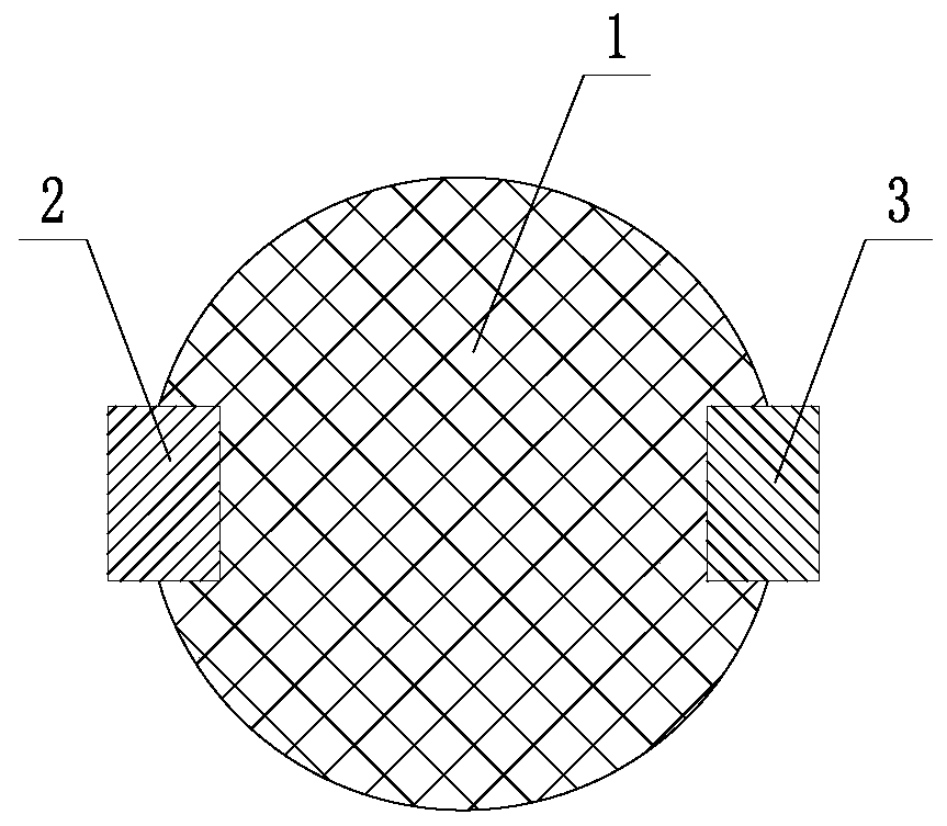
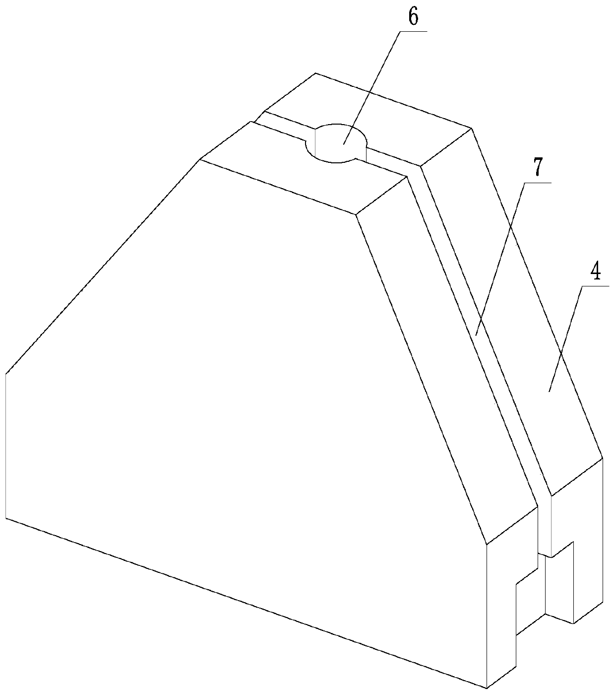
[0033] like Figures 1 to 6As shown, a multifunctional replaceable blasting electrode for plasma blasting experimental system includes a replaceable electrode assembly and a base assembly; the replaceable electrode assembly includes a polyethylene insulating rod 1 and a copper rod electrode, and the polyethylene insulating The outer surface of the rod 1 is provided with two copper rod electrode installation grooves, and the two copper rod electrode installation grooves are symmetrically distributed relative to the central axis of the polyethylene insulating rod 1; the number of the copper rod electrodes is two, and the two copper rod electrodes The electrodes are respectively embedded in two copper rod electrode installation grooves, and the two copper rod electrodes are respectively used as the positive copper rod 2 and the negative ...


PUM


Abstract

The invention relates to a multifunctional replacing-type blasting electrode for a plasma blasting experimental system. The multifunctional alternate-form blasting electrode comprises a replaceable electrode assembly and a base assembly. The replaceable electrode assembly comprises a polyethylene insulating rod and copper rod electrodes, wherein two electrode mounting grooves are formed in the surface of the insulating rod, and the copper rod electrodes are positioned in the grooves and are symmetrically distributed. The base assembly comprises a phenolic plastic material base body and a copper conductive part, an electrode assembly inserting hole is formed in the top of the base body, two conductive part mounting grooves are formed in the waist part of the base body, and the replaceable electrode assembly is matched with the electrode assembly inserting hole in an inserting-installing mode. One end of an electrode lead of the copper conductive part is positioned in the electrode assembly inserting hole and is in plug connection matching with the copper rod electrode, and the other end of the electrode lead is fixedly connected with a disc-shaped joint. A connecting screw is fixedly connected with the disc-shaped joint, and a connecting nut sleeves the connecting screw. The conductive part mounting grooves are equipped with insulating cover plates. The multifunctional replacing-type blasting electrode has the characteristics of small size, simple preparation process and high repeated utilization rate, both columnar explosive bags and spherical explosive bags can be simulated, and the manufacturing cost is lower.

Description

technical field [0001] The invention belongs to the technical field of rock mechanics and mining engineering, in particular to a multifunctional replaceable blasting electrode used in a plasma blasting experiment system. Background technique [0002] As an efficient rock-breaking method, the drill-and-blast method has been widely used in hard rock mine excavation and mining engineering and a large number of geotechnical engineering. The process of gas interaction has always been the focus of people's research, and the physical experiment of similar materials is one of the important methods to study rock and soil blasting engineering. [0003] Due to the flammable, explosive and other high-risk properties of explosives and their easy mobility, the country has strictly managed and controlled the use of civil explosive materials. Units without relevant qualifications cannot obtain and use explosives and other related civil explosive materials. Most universities and scientific ...

Claims


Application Information

Patent Timeline
IPC IPC(8): F42D1/00H01R13/02H01R13/42
Inventor 邱兆国杜川韩周洪杨晓辉郝红泽张凤鹏彭建宇闫广亮戴星航
Owner NORTHEASTERN UNIV
Learn More