Development layer series combination determination method and device, equipment and storage medium
A layer-system combination and layer-development technology, applied in design optimization/simulation, instrumentation, electrical digital data processing, etc., to achieve the effect of improving accuracy
Pending Publication Date: 2022-08-02
PETROCHINA CO LTD
0 Cites 0 Cited by
AI-Extracted Technical Summary
Problems solved by technology
[0004] However, the above scheme requires technicians to manually analyze the relevant information of each layer to determine the layer ...
Method used
In order to mobilize the enthusiasm of each oil reservoir to produce oil, the oil reservoirs with similar properties such as oil field underground permeability and little difference in extension distribution and similar reservoir pressure are combined together, and are developed with the same set of well patterns. When developing some multi-layer oilfields with extremely rich geological reserves, the multi-oil layers can be divided into several layers according to the nature of the oil layers, and a set of well pattern is drilled for each layer, and developed separately. This method is called division. Development layers. For each set of development strata, a suitable development method and well pattern deployment should be adopted, which can reduce the mutual interference between good oil layers and poor oil layers, and have a good effect on improving oil recovery speed and recovery factor.
In summary, the scheme shown in the embodiments of the present disclosure, by dividing the reservoir of the target block into a plurality of sublayers comprising one or more single sand layers respectively, and based on each single sand layer Geological parameters, to determine the difference of geological parameters in each sub-layer, and then divide multiple sub-layers according to various possible divisions to obtain a variety of layer combinations, and then calculate the difference between layers in various layer combinations The coefficient of variation between layers, that is, whether the differences in geological parameters are similar among layers, is used to quantitatively measure the advantages and disadvantages of various layer combinations, so as to accurately determine the optimal layer combination and improve the determination of layer combinations. accurac...
Abstract
The invention discloses a development layer series combination determination method, device and equipment and a storage medium, and belongs to the technical field of oil and gas exploitation. The method comprises the following steps: acquiring hierarchical division information of a target block, wherein the hierarchical division information is used for indicating at least two small layers in the target block; each small layer of the at least two small layers comprises at least one single sand layer; geological parameters of each single sand layer in the at least two small layers are obtained; obtaining respective total variable coefficients of the at least two small layers; obtaining at least two strata series combinations; according to the respective total variation coefficient of the at least two small layers, acquiring the variation coefficient between the strata series of each strata series combination in the at least two strata series combinations; and determining a target layer series combination from the at least two layer series combinations according to the inter-layer series variation coefficient of each layer series combination in the at least two layer series combinations. According to the scheme, the optimal series of strata combination is accurately determined, and the determination accuracy of the series of strata combination is improved.
Application Domain
Design optimisation/simulationSpecial data processing applications
Technology Topic
PhysicsPetroleum engineering
Image
Examples
- Experimental program(1)
Example Embodiment
[0032] Exemplary embodiments will be described in detail herein, examples of which are illustrated in the accompanying drawings. Where the following description refers to the drawings, the same numerals in different drawings refer to the same or similar elements unless otherwise indicated. The implementations described in the illustrative examples below are not intended to represent all implementations consistent with this disclosure. Rather, they are merely examples of apparatus and methods consistent with some aspects of the present disclosure as recited in the appended claims.
[0033] It should be understood that reference herein to "several" refers to one or more, and "plurality" refers to two or more. "And/or", which describes the association relationship of the associated objects, means that there can be three kinds of relationships, for example, A and/or B, which can mean that A exists alone, A and B exist at the same time, and B exists alone. The character "/" generally indicates that the associated objects are an "or" relationship.
[0034] In order to make the purposes, technical solutions and advantages of the embodiments of the present disclosure clearer, the technical solutions in the embodiments of the present disclosure will be described clearly and completely below with reference to the accompanying drawings in the embodiments of the present disclosure. Obviously, the described embodiments These are some, but not all, embodiments of the present disclosure. The components of the disclosed embodiments generally described and illustrated in the drawings herein may be arranged and designed in a variety of different configurations.
[0035] Therefore, the following detailed description of the embodiments of the disclosure provided in the accompanying drawings is not intended to limit the scope of the disclosure as claimed, but is merely representative of selected embodiments of the disclosure. Based on the embodiments in the present disclosure, all other embodiments obtained by those of ordinary skill in the art without creative efforts shall fall within the protection scope of the present disclosure.
[0036] It should be noted that the embodiments of the present disclosure and the features of the embodiments may be combined with each other under the condition of no conflict.
[0037] It should be noted that like numerals and letters refer to like items in the following figures, so once an item is defined in one figure, it does not require further definition and explanation in subsequent figures.
[0038] In the description of the embodiments of the present disclosure, it should be noted that the indicated azimuth or positional relationship is based on the azimuth or positional relationship shown in the accompanying drawings, or the azimuth or positional relationship that the product is usually placed in use, or the related art Orientation or positional relationship commonly understood by the skilled person, or the orientation or positional relationship that is usually placed when the product is used, is only for the convenience of describing the present disclosure and simplifying the description, rather than indicating or implying that the referred device or element must have a specific orientation, construction and operation in a particular orientation, and therefore should not be construed as a limitation of the present disclosure. In addition, the terms "first" and "second" are only used to differentiate the description, and should not be construed as indicating or implying relative importance.
[0039] In the description of the embodiments of the present disclosure, it should also be noted that, unless otherwise expressly specified and limited, the terms "arrangement" and "connection" should be understood in a broad sense, for example, it may be a fixed connection or a detachable connection , or integrally connected; it can be a direct connection or an indirect connection through an intermediate medium. For those of ordinary skill in the art, the specific meanings of the above terms in the present disclosure can be understood under specific circumstances; the accompanying drawings in the embodiments are used to clearly and completely describe the technical solutions in the embodiments of the present disclosure. The described embodiments are some, but not all, of the embodiments of the present disclosure. The components of the disclosed embodiments generally described and illustrated in the drawings herein may be arranged and designed in a variety of different configurations.
[0040]Fault block oil and gas reservoirs refer to oil and gas reservoirs formed by the accumulation of oil and gas in fault block traps. Also known as fault block trap oil and gas reservoirs. Fault block traps refer to the traps formed by the reservoir blocks that are cut by the intersection of two or more faults along the updip direction of the reservoir and have shielding and sealing against oil and gas. Fault-block oil and gas reservoirs can be further divided into step-shaped fault blocks, roof-shaped fault blocks, horst-shaped fault blocks, intersecting fault blocks, arc-shaped fault blocks, overthrust fault blocks, and closed fault blocks according to the combination of fault plane and section. oil and gas reservoirs.
[0041] Development formations refer to a group of oil and gas formations with the same properties that can be developed by the same well pattern. When developing multi-layer oilfields, it is very important to rationally divide and combine development layers according to the characteristics of different development layers to improve oil recovery.
[0042] The oil layer underground in an oilfield is usually not only one layer, but many oil layers, some dozens or dozens of layers, and the properties of each oil layer are different. Some oil layers have good permeability, high oil layer pressure and high oil saturation; some oil layers have poor permeability, low pressure and low oil saturation. If these many oil layers are mined together without distinguishing between good and bad, it will cause some layers to produce more oil, and some layers to produce less or even no oil.
[0043] In order to mobilize the enthusiasm of each oil layer to produce oil, the oil layers with similar properties such as underground permeability and little difference in extension distribution and similar oil layer pressure are grouped together, and the same well pattern is used for development. When developing some multi-layer oilfields with extremely rich geological reserves, the multi-oil layers can be divided into several layers according to the properties of the oil layers, and a set of well patterns shall be drilled separately for each layer to develop separately. This method is called division development layer. For each set of development layers, appropriate development methods and well pattern deployment should be adopted, which can reduce the mutual interference between good oil layers and bad oil layers, and have a good effect on improving oil production rate and recovery factor.
[0044] Reasonable division of development layers is to combine oil layers with similar characteristics, develop them with a single development system, and carry out production planning, dynamic research and adjustment based on this, which is conducive to giving full play to the role of various oil layers.
[0045] In the same oilfield, because the sedimentary environment and conditions of the reservoirs in the vertical direction cannot be completely consistent, the characteristics of the reservoirs will naturally be different, so the contradiction between layers will inevitably appear in the development process. If the development layers cannot be properly combined and divided, it will be a major misstep in development, which will cause major problems in oilfield production and affect the development effect. For example, when the high-permeability layer and the low-permeability layer are produced together, the production capacity of the low-permeability layer is often limited due to the large oil flow resistance; when the low-pressure layer and the high-pressure layer are produced together, the low-pressure layer often produces no oil, and even the oil in the high-pressure layer is produced. It is possible to break into the low-pressure layer; in water-flooding oilfields, the high-permeability layer is often flooded quickly, and in the case of commingled production, the contradiction between layers will be aggravated, and the mutual interference of oil and water layers will occur, which will seriously affect the recovery factor.
[0046] The division of development layers is the basis for deploying well patterns and planning production facilities. Once the development layers are determined, the number of well pattern sets is generally determined, thus making it possible to study and deploy well patterns, injection-production methods, and the planning and construction of surface production facilities.
[0047] The development level of oil production technology requires the division of layers. In a multi-layer oil field, the number of oil layers is often as many as dozens, and the mining well interval can sometimes reach hundreds of meters. In order to give full play to the role of each oil layer, make them absorb water evenly and produce oil evenly, the measures of layered water injection, layered oil recovery and layered control are often adopted in the oil recovery process. Therefore, it is necessary to divide the development layers, so that the number of oil layers in a development layer system is not too much, and the well section is not too long, so as to better play the role of technological means and develop the oil field well.
[0048] The high-speed development of oilfields requires the division of layers. Using a set of well patterns to develop a multi-layer oilfield will inevitably fail to give full play to the role of each oil layer, especially when there are many major oil-producing layers, in order to give full play to the role of each oil layer, it is necessary to divide the development layers. Only in this way can the rate of oil extraction be increased, the production of the oil field be accelerated, the development time can be shortened, and the turnover rate of the capital investment can be improved.
[0049] Complex fault-block reservoirs are characterized by the development of faults on the plane, and there are multiple sets of oil-water system combinations in the vertical direction. The oil interval spans are large, the number of layers is large, and the reservoir heterogeneity is strong. In the process of water flooding development, this type of oil reservoir is affected by the heterogeneity of the reservoir, the water cut rises rapidly, the injected water inrushes in a single layer, the production degree of the oil layer decreases, and the remaining oil is highly scattered in spatial distribution; with the extension of the development time , the interlayer interference is becoming more and more serious, and the original development layer system can no longer meet the requirements of enhanced oil recovery.
[0050] At present, the conventional methods for determining the scheme of formation reorganization are mainly based on the fine geological research, using conventional reservoir engineering methods and reservoir numerical simulation methods. The former mainly analyzes the feasibility of formation combination from the aspects of production degree, interlayer, fluid properties and remaining resources. Differentiation and comparison, and the subjective factors of decision makers are strong; although the reservoir numerical simulation method can comprehensively consider many factors affecting the development effect after the formation combination, it can compare and optimize various formation combination methods, but it takes a long time. , which greatly affects the work efficiency. In general, the current optimization method of the layer system reorganization scheme cannot take into account the two aspects of efficiency and effect.
[0051] The purpose of the present disclosure is to provide a fast, simple and optimal method for formation reorganization, thereby improving the development effect of the oil reservoir and increasing the recovery rate of the oil reservoir.
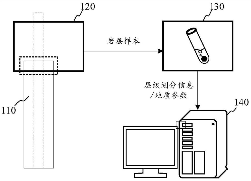
[0052] figure 1 It is a schematic diagram of a system for determining a combination of development layers according to an exemplary embodiment. The development formation combination determination system includes a well 110 , a well sampling device 120 , an experimental testing device 130 , and a computer device 140 .
[0053] The drilling sampling device 120 is arranged at the wellhead of the drilling well 110 and is used for sampling various data and samples of the drilling well 110 , for example, collecting samples of rock formations in the drilling well 110 .
[0054] The experimental testing equipment 130 is used to perform experimental tests on rock formation samples under manual operation or automatic operation to determine various geological information, such as layer division information of rock formations, geological parameters of each single sand layer, and the like.
[0055] The experimental test equipment 130 may be equipment in a laboratory in a temporary or fixed setting.
[0056] The computer device 140 is used to determine the final development layer series combination based on the data obtained by the experimental test device 130 .
[0057] The computer program/software for determining the combination of development layers may be installed in the computer device 140 .
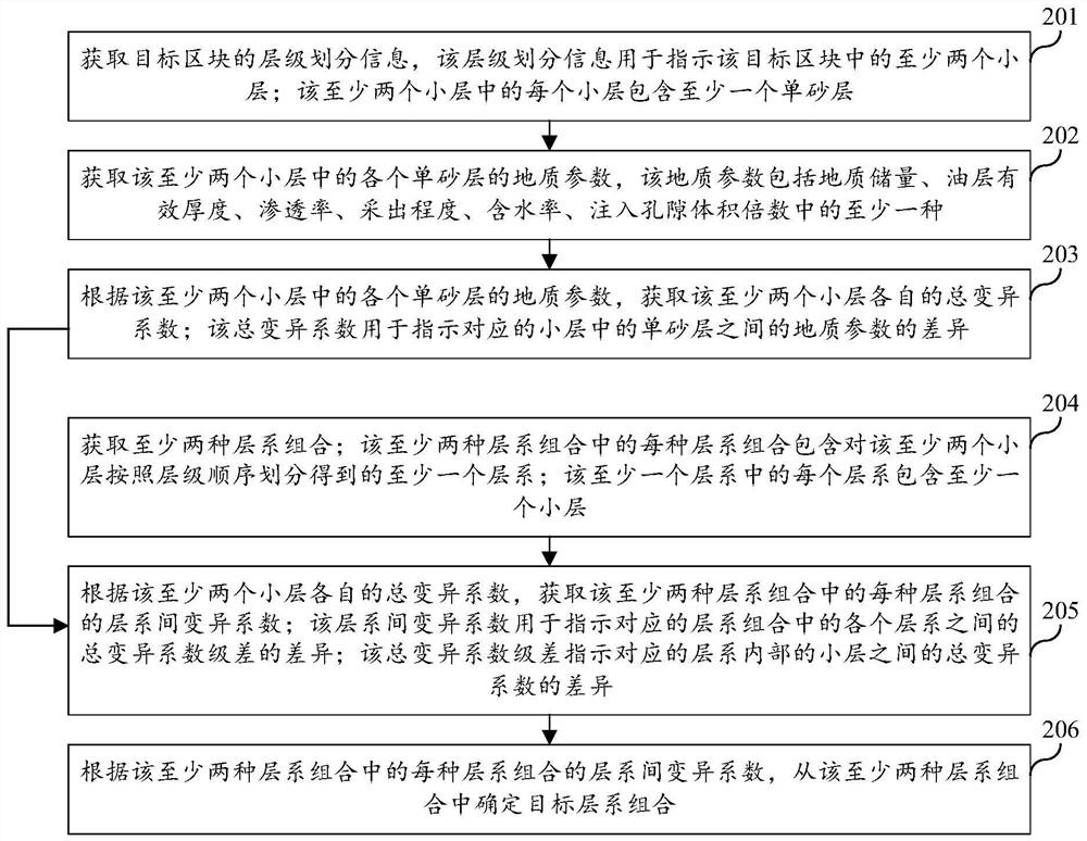
[0058] figure 2 It is a flow chart of a method for determining a method for developing a layer system combination according to an exemplary embodiment. like figure 2 As shown, the method for determining the combination of development layers includes the following steps:
[0059] Step 201: Obtain hierarchical division information of a target block, where the hierarchical division information is used to indicate at least two sublayers in the target block; each sublayer in the at least two sublayers includes at least one single sand layer.
[0060] Step 202: Obtain geological parameters of each single sand layer in the at least two sublayers, where the geological parameters include at least one of geological reserves, effective thickness of oil layers, permeability, recovery degree, water content, and injection pore volume multiple .
[0061] Step 203, according to the geological parameters of each single sand layer in the at least two sublayers, obtain the total variation coefficient of each of the at least two sublayers; the total variation coefficient is used to indicate the difference between the single sand layers in the corresponding sublayers. differences in geological parameters.
[0062] Step 204: Obtain at least two layer series combinations; each layer series combination in the at least two layer series combinations includes at least one layer series obtained by dividing the at least two sublayers according to the hierarchical order; in the at least one layer series Each layer series contains at least one sublayer.
[0063] Step 205: Obtain the inter-layer variation coefficient of each layer combination in the at least two layer combinations according to the respective total variation coefficients of the at least two sublayers; the inter-layer variation coefficient is used to indicate the corresponding layer The difference in the total coefficient of variation difference between the layers in the series combination; the total coefficient of variation difference indicates the difference in the total coefficient of variation between sublayers within the corresponding layer series.
[0064] Step 206: Determine a target layer combination from the at least two layer combinations according to the inter-layer variation coefficient of each layer combination in the at least two layer combinations.
[0065] To sum up, the solutions shown in the embodiments of the present disclosure divide the reservoir of the target block into multiple sub-layers containing one or more single sand layers respectively, and based on various geological parameters of each single sand layer , determine the difference of geological parameters in each sublayer, and then divide multiple sublayers according to various possible divisions to obtain a variety of strata combinations, and then calculate the layers between the strata in the various strata combinations. The coefficient of variation between series, that is, whether the differences in geological parameters are similar between each layer series, can quantitatively measure the pros and cons of multiple layer series combinations, so as to accurately determine the optimal layer series combination and improve the accuracy of layer series combination determination. .
[0066] On the basis of reservoir engineering research, the present disclosure comprehensively considers various factors reflecting the contradiction of reservoir layers, such as reservoir physical properties, reservoir thickness, geological reserves, single-layer production degree, water-out status, oil layer thickness, etc. Various dynamic and static indicators adopt the summation method of coefficient of variation, and the indicators are quantified and comprehensively considered for layer division. This scheme takes the small layer as the minimum calculation unit, and is suitable for the optimal combination of oil layers with more than one single sand layer in the small layer.
[0067] The present disclosure combines layers with similar physical properties and producing conditions to ensure low interlayer heterogeneity; statically selects permeability, thickness, and reserves, and considers recovery degree, water content, and injection volume multiple for dynamic parameters. The present disclosure solves the technical problems of inaccurate layer division caused by the single layer combination scheme in the prior art, it is difficult to distinguish and compare the pros and cons of multiple layer combination methods, and the human subjective factors are strong.
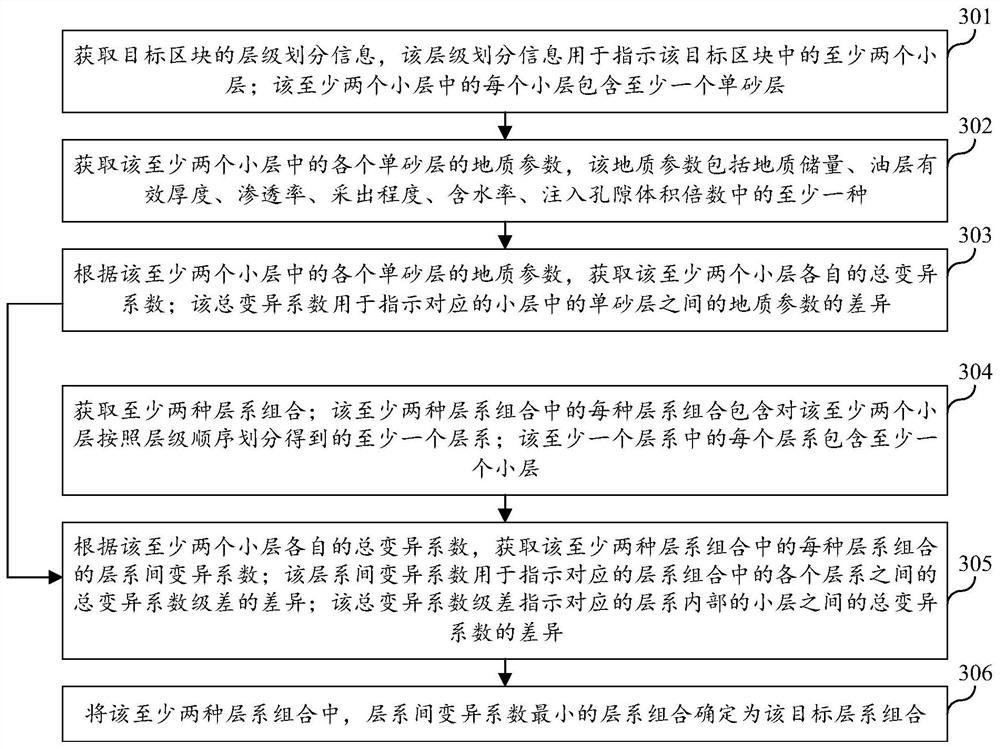
[0068] image 3 It is a flow chart of a method for determining a method for developing a layer system combination according to an exemplary embodiment. like image 3 As shown, the method for determining the combination of development layers includes the following steps:
[0069] Step 301: Obtain hierarchical division information of a target block, where the hierarchical division information is used to indicate at least two sublayers in the target block; each sublayer in the at least two sublayers includes at least one single sand layer.
[0070] In the embodiments of the present disclosure, on the basis of fine stratigraphic comparison, firstly, sub-layers are divided, and then the development unit is subdivided into a single sand layer.
[0071] Strata is the general term for all stratiform rocks, including metamorphic and volcanic stratiform rocks. A stratum is a layer or a group of rock formations that have some uniform characteristics and properties and are clearly distinct from the upper and lower layers. Adjacent strata may be separated by distinct layers or sedimentary discontinuities, or by some less distinct boundaries. Formations can be either consolidated rock or loose deposits.
[0072] Stratigraphic correlation is one of the important means of studying strata. Its significance is to compare some stratigraphic units in different regions according to the characteristics of lithology and the fossils contained in them, so as to prove that these stratigraphic units are equivalent in layers. Yes, close in time.
[0073] The development stratum is a set of oil-gas-bearing layer combinations between sand and mudstone, and it is a stratum that can be compared in the sedimentary basin.
[0074] On the full profile of a hydrocarbon-bearing formation, a certain logging curve has obvious segments. The lithology or lithology combination above and below these segments have obvious changes, and the oil-bearing grades are significantly different. At this time, they can be divided into different oil and gas layers. Group.
[0075] The sand layer group is obtained by dividing the adjacent oil and gas layers in the oil and gas layer group.
[0076] The sublayer is a small layer of oil and gas layers separated by impermeable layers above and below the sand layer group.
[0077] Step 302: Obtain geological parameters of each single sand layer in the at least two small layers, the geological parameters include at least one of geological reserves, effective thickness of oil layers, permeability, recovery degree, water content, and injection pore volume multiple .
[0078] In the embodiment of the present disclosure, fine reservoir evaluation can be carried out for a single sand layer, and the distribution status and physical properties of the interlayers of each single sand layer can be determined; and the research on the characteristics of fine oil reservoirs and the distribution law of remaining oil can be carried out to determine the Geological parameters such as geological reserves, effective thickness of oil layer, permeability, recovery degree, water content, and injection pore volume multiple.
[0079] Step 303: Obtain the respective total variation coefficients of the at least two sublayers according to the geological parameters of each single sand layer in the at least two sublayers; the total variation coefficient is used to indicate the difference between the single sand layers in the corresponding sublayers. differences in geological parameters.
[0080] In a possible implementation manner, according to the geological parameters of each single sand layer in the at least two sublayers, the respective total coefficients of variation of the at least two sublayers are obtained, including:
[0081] Obtain the variation coefficient of various geological parameters of the target sublayer; the variation coefficient is used to indicate the difference between the corresponding geological parameters in each single sand layer in the target sublayer; the target sublayer is the at least two sublayers any one of;
[0082] According to the variation coefficients of various geological parameters of the target sublayer, the total variation coefficient of the target sublayer is obtained.
[0083] In a possible implementation manner, the geological parameters include at least two of geological reserves, effective thickness of the oil layer, permeability, recovery degree, water cut, and injection pore volume multiple; the acquisition of various geological parameters of the target sublayer coefficient of variation, including:
[0084] Obtain the target geological parameters of each single sand layer in the target sublayer; the target geological parameters are any one of geological reserves, effective thickness of oil layer, permeability, recovery degree, water content, and injection pore volume multiple;
[0085] The coefficient of variation of the target geological parameter of the target sublayer is calculated by the following formula:
[0086]
[0087] Among them, C A Represents the coefficient of variation of the target geological parameter of the target sublayer; A j represents the target geological parameter of the jth single sand layer in the target sublayer; Represents the average value of the target geological parameters of each single sand layer in the target sublayer; n is the number of single sand layers in the target sublayer.
[0088] In a possible implementation manner, the total coefficient of variation of the target sublayer is obtained according to the coefficients of variation of various geological parameters of the target sublayer, including:
[0089] Add the variation coefficients of various geological parameters of the target sublayer to obtain the total variation coefficient of the target sublayer;
[0090] Or, take the weighted sum of the variation coefficients of various geological parameters of the target sublayer to obtain the total variation coefficient of the target sublayer;
[0091] Or, the variation coefficients of various geological parameters of the target sublayer are averaged to obtain the total variation coefficient of the target sublayer;
[0092] Alternatively, a weighted average of the variation coefficients of various geological parameters of the target sublayer is taken to obtain the total variation coefficient of the target sublayer.
[0093] In the embodiment of the present disclosure, the geological reserves, effective thickness of the oil layer, permeability, recovery degree, water cut, and multiplier variation coefficient of injected pore volume of the sublayer can be calculated, and the variation coefficients can be summed.
[0094] Calculate the coefficient of variation of each correlation factor for each sub-layer, and obtain the sum of the coefficient of variation of each sub-layer. Combined with the actual production situation of the oilfield, the interlayers between single sand layers are unstable, and the same sublayer is often not divided into different layers when the layers are divided. Therefore, the smallest unit of layer division is the sublayer, and the sublayer The coefficient of variation of geological parameters is obtained by means of a single sand layer, so this method is suitable for the division of reservoirs with more than 1 single sand layer in a small layer.
[0095] Assume that the sum of the coefficients of variation of the geological parameters of the ith sublayer Fi is:
[0096] F i =C ki +C hi +C Ri +C fi +C pvi +C Ni
[0097] Among them, C ki represents the coefficient of variation of permeability of the ith sublayer, and the data type is f; C hi Indicates the coefficient of variation of the effective thickness of the ith sublayer, and the data type is f; C Ri Represents the coefficient of variation of the recovery degree of the ith sublayer, and the data type is f; C fi Indicates the coefficient of variation of water content of the i-th sublayer, and the data type is f; C pvi Represents the coefficient of variation of the injected pore volume in the i-th sublayer, and the data type is f; C Ni Indicates the coefficient of variation of geological reserves of the i-th sublayer, and the data type is f.
[0098] The coefficient of variation of permeability in the above formula is:
[0099]
[0100] Among them, K ij Indicates the permeability of the jth single sand layer of the ith sublayer, in units of 10 -3 μm 2;
[0101] Indicates the average permeability of the ith sublayer, the unit is 10 -3 μm 2;
[0102] n i Indicates the number of single sand layers in the i-th small layer, in units.
[0103] The effective thickness variation coefficient is:
[0104]
[0105] where h ij Indicates the effective thickness of the jth single sand layer of the ith sublayer, in m;
[0106] Indicates the average effective thickness of the ith sublayer, the unit is 10 -3 μm 2;
[0107] The coefficient of variation of the recovery degree is:
[0108]
[0109] where R ij Represents the recovery degree of the jth single sand layer of the ith sublayer, the unit is %;
[0110] Indicates the average value of the recovery degree of the ith sublayer, the unit is %;
[0111] The comprehensive coefficient of variation of water content is:
[0112]
[0113] where f ij Indicates the comprehensive water content of the jth single sand layer of the ith sublayer, the unit is %;
[0114] Indicates the average value of the comprehensive water content of the i-th sublayer, in %;
[0115] The coefficient of variation of the injected pore volume is:
[0116]
[0117] Among them, pv ij Indicates the injection pore volume multiple of the jth single sand layer of the ith sublayer, and the data type is f;
[0118] Represents the average value of the injected pore volume in the i-th sublayer, and the data type is f;
[0119] The coefficient of variation of the geological reserves of the small layer is:
[0120]
[0121] Among them, N ij Indicates the injection pore volume multiple of the jth single sand layer of the ith sublayer, and the data type is f;
[0122] Indicates the average value of the injected pore volume in the ith sublayer, and the data type is f.
[0123] Step 304: Obtain at least two layer series combinations; each layer series combination in the at least two layer series combinations includes at least one layer series obtained by dividing the at least two sublayers according to the hierarchical order; in the at least one layer series Each layer series contains at least one sublayer.
[0124] In the embodiment of the present disclosure, all layer division schemes can be calculated by using a mathematical arrangement and combination.
[0125] Assuming that there are m small layers in the vertical direction of the block, they are divided into layer series 1, layer series 2, and layer series k from top to bottom. Layer 1 has m 1 A small layer, layer system 2 has m 2 a small layer, ..., the layer system k has m k a small layer. The small layer combination relationship satisfies m 1 +m 2 …+m k =m, and satisfies m which is continuous and gradually deepening in the layer system i A small layer, then the total number of combination schemes is:
[0126]
[0127] in, Indicates that m is arbitrarily selected from n small layers 1 The number of combinations of layers.
[0128] Step 305: Obtain the inter-layer variation coefficient of each layer combination in the at least two layer combinations according to the respective total variation coefficients of the at least two sublayers; the inter-layer variation coefficient is used to indicate the corresponding layer The difference in the total coefficient of variation difference between the strata in the line combination; the total coefficient of variation difference indicates the difference in the total coefficient of variation between sublayers within the corresponding stratum.
[0129] In a possible implementation manner, according to the respective total coefficients of variation of the at least two sublayers, the level difference of the total coefficient of variation of each layer combination in the at least two layer series combinations is obtained, including:
[0130] Calculate the total variation coefficient level difference of the sublayers within each layer series in the target layer series combination by the following formula:
[0131] B i =max(F mi )/min(F mi );
[0132] Among them, B i Represents the total variation coefficient level difference of the sub-layers within the i-th layer series in the target layer series combination; max(Fmi ) represents the maximum value of the total coefficient of variation of the sublayer within the i-th layer system in the target layer system combination; min(F mi ) represents the minimum value of the total coefficient of variation of the sublayer within the i-th layer system in the target layer system combination;
[0133] The inter-layer variation coefficient of the target layer combination is obtained according to the level difference of the total coefficient of variation of the sublayers within each layer in the target layer combination.
[0134] In a possible implementation manner, the inter-layer variation coefficient of the target layer combination is obtained according to the level difference of the total coefficient of variation of the sublayers within each layer in the target layer combination, including:
[0135] Taking the average value of the difference of the total coefficient of variation of the sub-layers within each layer in the target layer combination to obtain the inter-layer variation coefficient of the target layer combination.
[0136] In this embodiment of the present disclosure, the intra-layer variation coefficient and level difference B of each layer division scheme can be calculated i. Then calculate the coefficient of variation between layers for each layer division scheme. Assuming that the oil layer is divided into k layers, then:
[0137]
[0138] where V B Represents the coefficient of variation between scheme layers; Represents the mean value of the coefficient of variation and range within the scheme stratum.
[0139] Step 306 , among the at least two layer combinations, the layer combination with the smallest coefficient of variation between layer series is determined as the target layer combination.
[0140] In an embodiment of the present disclosure, V B The smaller the value is, the closer the physical properties and development status of the reservoirs are, the weaker the heterogeneity, and the better the combination of layers. When V B When there is more than one scheme with the smallest number, the scheme with the least number of layers (the most cost-effective) is selected as the optimal layer combination (ie, the above-mentioned target layer combination).
[0141] Taking the strata optimization of the fine oil reservoir of the D oilfield, the description of the IV oil group as an example:
[0142] The fine oil reservoir in D oilfield is divided into 4 sub-layers and 15 single sand layers, and the geological reserves, effective thickness of oil layers, permeability, recovery degree, water content and injection pore volume multiple of each single sand layer are determined. , see Table 1.
[0143] Table 1
[0144]
[0145] The coefficients of variation of the six parameters of each sub-layer were obtained respectively, as shown in Table 2.
[0146] Table 2
[0147]
[0148] The sums of the coefficients of variation of the 6 parameters of the 4 sub-layers are obtained respectively, as shown in Table 3.
[0149] table 3
[0150] Sublayer serial number small layer Coefficient of variation and /Fi ① Columbine IV-1 1.11 ② Columbine IV-2 1.18 ③ Columbine IV-3 0.80 ④ Columbine IV-4 0.86
[0151] List all layer division schemes.
[0152] Calculate the combination scheme of all layer series, and at the same time, according to the actual situation, the small layers in the layer series must ensure continuous distribution from top to bottom, delete the unsatisfactory scheme, then all the layer series division scheme (small layer is replaced by small layer serial number) There are 7 (When the number of small layers is large, the acquisition of all layer combination schemes can be done with the help of a computer). See Table 4.
[0153] Table 4
[0154] Scheme name plan 1 Scenario 2 Scenario 3 Scenario 4 Scenario 5 Option 6 Option 7 Layer combination ①/②③④ ①②/③④ ①②③/④ ①/②/③④ ①/②③/④ ①②/③/④ ①/②/③/④
[0155] The optimal layer division scheme is preferred. The coefficient of variation between the layers of each scheme was calculated, and the calculation results showed that the coefficient of variation between the layers of scheme 2 and scheme 7 was the smallest, which was 0. At the same time, considering the cost-effectiveness, the scheme with few layers was selected, and the scheme 2 was finally determined as the best layer division scheme, as shown in Table 5.
[0156] table 5
[0157]
[0158] To sum up, the solutions shown in the embodiments of the present disclosure divide the reservoir of the target block into multiple sub-layers containing one or more single sand layers respectively, and based on various geological parameters of each single sand layer , determine the difference of geological parameters in each sublayer, and then divide multiple sublayers according to various possible divisions to obtain a variety of strata combinations, and then calculate the layers between the strata in the various strata combinations. The coefficient of variation between series, that is, whether the differences in geological parameters are similar between each layer series, can quantitatively measure the pros and cons of multiple layer series combinations, so as to accurately determine the optimal layer series combination and improve the accuracy of layer series combination determination. .
[0159] In the solutions shown in the above embodiments of the present disclosure, the process of determining the combination of layers by using the geological parameters of each single sand layer can be performed by computer equipment. For example, after obtaining the above-mentioned geological parameters of each single sand layer through stratigraphic comparison and testing, the technical personnel input the geological parameters into the computer equipment, and the computer equipment automatically determines the formation combination according to the evaluation information.
[0160] Figure 4 is a block diagram of a device for determining a combination of development layers according to an exemplary embodiment, such as Figure 4 As shown, the apparatus for determining the combination of development layers can be implemented as all or part of a computer device by means of hardware or a combination of software and hardware, so as to execute figure 2 or image 3 All or part of the steps of the methods shown in the corresponding embodiments. The device for determining the combination of development layers may include:
[0161] The hierarchical division information acquisition module 401 is configured to acquire hierarchical division information of a target block, where the hierarchical division information is used to indicate at least two sub-layers in the target block; each of the at least two sub-layers The sublayer contains at least one single sand layer;
[0162] Geological parameter acquisition module 402, configured to acquire geological parameters of each single sand layer in the at least two sublayers, the geological parameters include geological reserves, effective thickness of oil layers, permeability, recovery degree, water content, injection pores At least one of the volume multiples;
[0163] The total variation coefficient obtaining module 403 is configured to obtain the respective total variation coefficients of the at least two sublayers according to the geological parameters of each single sand layer in the at least two sublayers; the total variation coefficients are used to indicate the corresponding The difference in geological parameters between the single sand layers in the sublayers;
[0164] A layer series combination obtaining module 404, configured to obtain at least two layer series combinations; each layer series combination in the at least two layer series combinations includes at least one layer obtained by dividing the at least two sublayers in hierarchical order series; each layer series in the at least one layer series comprises at least one sublayer;
[0165] The inter-layer variation coefficient obtaining module 405 is configured to obtain the inter-layer variation coefficient of each layer combination in the at least two layer combinations according to the respective total variation coefficients of the at least two sublayers; the The coefficient of variation between layers is used to indicate the difference in the difference of the total coefficient of variation between each layer in the corresponding layer combination; the difference of the total coefficient of variation indicates the difference of the total coefficient of variation between the small layers within the corresponding layer. difference;
[0166] The target layer series combination determination module 406 is configured to determine a target layer series combination from the at least two layer series combinations according to the inter-layer series variation coefficient of each layer series combination of the at least two layer series combinations.
[0167] In a possible implementation manner, the total coefficient of variation obtaining module 403 is used to:
[0168] Obtain the variation coefficients of various geological parameters of the target sublayer; the variation coefficients are used to indicate the differences of the corresponding geological parameters among each single sand layer in the target sublayer; the target sublayer is the at least one either of the two sublayers;
[0169] According to the coefficients of variation of various geological parameters of the target sublayer, the total coefficient of variation of the target sublayer is obtained.
[0170] In a possible implementation manner, the total coefficient of variation obtaining module 403 is used to:
[0171] Obtain the target geological parameters of each single sand layer in the target sublayer; the target geological parameters are any one of geological reserves, effective thickness of oil layer, permeability, degree of recovery, water content, and injection pore volume multiple;
[0172] The coefficient of variation of the target geological parameter of the target sublayer is calculated by the following formula:
[0173]
[0174] Among them, C A Represents the coefficient of variation of the target geological parameter of the target sublayer; A j represents the target geological parameter of the jth single sand layer in the target sublayer; represents the average value of the target geological parameters of each single sand layer in the target sublayer; n is the number of single sand layers in the target sublayer.
[0175] In a possible implementation manner, the total coefficient of variation obtaining module 403 is used to:
[0176] adding the coefficients of variation of various geological parameters of the target sublayer to obtain the total coefficient of variation of the target sublayer;
[0177] Or, taking the weighted sum of the coefficients of variation of various geological parameters of the target sublayer to obtain the total coefficient of variation of the target sublayer;
[0178] Or, taking the average value of the variation coefficients of various geological parameters of the target sublayer to obtain the total variation coefficient of the target sublayer;
[0179] Alternatively, the coefficient of variation of various geological parameters of the target sublayer is weighted and averaged to obtain the total coefficient of variation of the target sublayer.
[0180] In a possible implementation manner, the inter-layer variation coefficient obtaining module 405 is used to:
[0181] Calculate the total variation coefficient level difference of the sublayers within each layer series in the target layer series combination by the following formula:
[0182] B i =max(F mi )/min(F mi );
[0183] Among them, B i Represents the total variation coefficient level difference of the sub-layers within the i-th layer series in the target layer series combination; max(F mi ) represents the maximum value of the total coefficient of variation of the sublayer within the i-th layer system in the target layer system combination; min(F mi ) represents the minimum value of the total coefficient of variation of the sublayer within the i-th layer system in the target layer system combination;
[0184] The inter-layer variation coefficient of the target layer combination is obtained according to the level difference of the total coefficient of variation of the sublayers within each layer in the target layer combination.
[0185] In a possible implementation manner, the inter-layer variation coefficient obtaining module 405 is used to:
[0186] Taking the average value of the difference of the total coefficient of variation of the sub-layers within each layer in the target layer combination to obtain the inter-layer variation coefficient of the target layer combination.
[0187]In a possible implementation manner, the target layer series combination determination module 406 is configured to determine the layer series combination with the smallest coefficient of variation between layer series among the at least two layer series combinations as the target layer series combination .
[0188] To sum up, the solutions shown in the embodiments of the present disclosure divide the reservoir of the target block into multiple sub-layers containing one or more single sand layers respectively, and based on various geological parameters of each single sand layer , determine the difference of geological parameters in each sublayer, and then divide multiple sublayers according to various possible divisions to obtain a variety of strata combinations, and then calculate the layers between the strata in the various strata combinations. The coefficient of variation between series, that is, whether the differences in geological parameters are similar between each layer series, can quantitatively measure the pros and cons of multiple layer series combinations, so as to accurately determine the optimal layer series combination and improve the accuracy of layer series combination determination. .
[0189] It should be noted that, when the device provided in the above embodiment realizes its functions, only the division of the above functional modules is used as an example for illustration. In practical applications, the above functions can be allocated to different functional modules according to actual needs. That is, the content structure of the device is divided into different functional modules to complete all or part of the functions described above.
[0190] Regarding the apparatus in the above-mentioned embodiment, the specific manner in which each module performs operations has been described in detail in the embodiment of the method, and will not be described in detail here.
[0191] Figure 5 It is a schematic structural diagram of a computer device according to an exemplary embodiment. The computer device 500 includes a Central Processing Unit (CPU) 501, a system memory 504 including a Random Access Memory (RAM) 502 and a Read-Only Memory (ROM) 503, and A system bus 505 that connects the system memory 504 and the central processing unit 501 . The computer device 500 also includes a basic input/output system (Input/Output, I/O system) 506 that helps to transfer information between various devices within the computer device, and is used to store an operating system 513, application programs 514 and other programs Mass storage device 507 of module 515 .
[0192] The basic input/output system 506 includes a display 508 for displaying information and input devices 506 such as a mouse, keyboard, etc., for user input of information. The display 508 and the input device 509 are both connected to the central processing unit 501 through the input and output controller 510 connected to the system bus 505 . The basic input/output system 506 may also include an input output controller 510 for receiving and processing input from a number of other devices such as a keyboard, mouse, or electronic stylus. Similarly, input output controller 510 also provides output to a display screen, printer, or other type of output device.
[0193] The mass storage device 507 is connected to the central processing unit 501 through a mass storage controller (not shown) connected to the system bus 505 . The mass storage device 507 and its associated computer device-readable media provide non-volatile storage for the computer device 500 . That is, the mass storage device 507 may include a computer device readable medium (not shown) such as a hard disk or a Compact Disc Read-Only Memory (CD-ROM) drive.
[0194] Without loss of generality, the computer device readable medium may include computer device storage media and communication media. Computer device storage media includes volatile and nonvolatile, removable and non-removable media implemented in any method or technology for storage of information such as computer device readable instructions, data structures, program modules or other data. The storage medium of computer equipment includes RAM, ROM, Erasable Programmable ReadOnly Memory (EPROM), Electrically Erasable Programmable Read-Only Memory (EEPROM), CD-ROM, digital Digital Video Disc (DVD) or other optical storage, cassette, magnetic tape, magnetic disk storage or other magnetic storage device. Of course, those skilled in the art know that the storage medium of the computer device is not limited to the above-mentioned ones. The system memory 504 and the mass storage device 507 described above may be collectively referred to as memory.
[0195] According to various embodiments of the present disclosure, the computer device 500 may also operate by connecting to a remote computer device on a network through a network such as the Internet. That is, the computer device 500 can be connected to the network 512 through the network interface unit 511 connected to the system bus 505, or in other words, the network interface unit 511 can also be used to connect to other types of networks or remote computer device systems (not shown). out).
[0196] The memory also includes one or more programs, the one or more programs are stored in the memory, and the central processing unit 501 realizes by executing the one or more programs figure 2 or image 3 All or part of the steps of the method shown.
[0197] Those skilled in the art should realize that, in one or more of the above examples, the functions described in the embodiments of the present disclosure may be implemented by hardware, software, firmware, or any combination thereof. When implemented in software, the functions may be stored on or transmitted over as one or more instructions or code on a computer device-readable medium. Computer device-readable media includes both computer device storage media and communication media including any medium that facilitates transfer of a program for a computer device from one place to another. A storage medium can be any available medium that can be accessed by a general purpose or special purpose computer device.
[0198] An embodiment of the present disclosure also provides a computer device, the computer device includes a processor and a memory, and the memory stores at least one instruction, at least one piece of program, code set or instruction set, the at least one instruction, the at least one piece of program, The code set or instruction set is loaded and executed by the processor to implement the above-mentioned method for determining the combination of development layers.
[0199] Embodiments of the present disclosure further provide a computer-readable storage medium, where at least one instruction, at least one piece of program, code set or instruction set is stored in the storage medium, the at least one instruction, the at least one piece of program, the code set or instruction set The set is loaded and executed by the processor to implement the above-described method for determining the combination of development layers.
[0200] Embodiments of the present disclosure also provide a computer program product or computer program, where the computer program product or computer program includes computer instructions, and the computer instructions are stored in a computer-readable storage medium. The processor of the computer device reads the computer instructions from the computer-readable storage medium, and the processor executes the computer instructions, so that the computer device executes the above-mentioned method for determining the combination of development layers.
[0201] Other embodiments of the present disclosure will readily occur to those skilled in the art upon consideration of the specification and practice of the invention disclosed herein. This disclosure is intended to cover any variations, uses, or adaptations of this disclosure that follow the general principles of this disclosure and include common general knowledge or techniques in the technical field not disclosed by this disclosure . The specification and examples are to be regarded as exemplary only, with the true scope and spirit of the disclosure being indicated by the following claims.
[0202] It is to be understood that the present disclosure is not limited to the precise structures described above and illustrated in the accompanying drawings, and that various modifications and changes may be made without departing from the scope thereof. The scope of the present disclosure is limited only by the appended claims.
PUM


Description & Claims & Application Information
We can also present the details of the Description, Claims and Application information to help users get a comprehensive understanding of the technical details of the patent, such as background art, summary of invention, brief description of drawings, description of embodiments, and other original content. On the other hand, users can also determine the specific scope of protection of the technology through the list of claims; as well as understand the changes in the life cycle of the technology with the presentation of the patent timeline. Login to view more.
Similar technology patents
Metrology Method and Apparatus, Substrate, Lithographic System and Device Manufacturing Method
Owner:ASML NETHERLANDS BV
Intelligent protocol parsing method and device
Owner:BEIJING VENUS INFORMATION TECH
TR309 - portable otoscope video viewer
Owner:RICH TONY C +1
Communication terminal apparatus and communication system
Owner:SONY ERICSSON MOBILE COMM JAPAN INC
Classification and recommendation of technical efficacy words
- improve accuracy
Golf club head with adjustable vibration-absorbing capacity
Owner:FUSHENG IND CO LTD
Direct fabrication of aligners for arch expansion
Owner:ALIGN TECH
Stent delivery system with securement and deployment accuracy
Owner:BOSTON SCI SCIMED INC
Method for improving an HS-DSCH transport format allocation
Owner:NOKIA SOLUTIONS & NETWORKS OY
Catheter systems
Owner:ST JUDE MEDICAL ATRIAL FIBRILLATION DIV