Fluid connector including retaining cartridge

A connector, fluid technology, used in non-removable pipe connections, couplings, pipes/pipe joints/fittings, etc., can solve problems such as easy loss, jeopardizing the structural integrity of the retaining clip, etc.

Pending Publication Date: 2022-08-02
OTIKER NJ INK
View PDF0 Cites 0 Cited by
  • Summary
  • Abstract
  • Description
  • Claims
  • Application Information

AI Technical Summary

Problems solved by technology

However, for a fluid connector to function properly, a slot or aperture must be machined into the connector body to allow the retaining clip to protrude through and engage the end molding, which requires additional post-processing machining
Additionally, it is diffic...

Method used


Image

  • Fluid connector including retaining cartridge
  • Fluid connector including retaining cartridge
  • Fluid connector including retaining cartridge

Examples


Embodiment Construction

[0029] At the outset, it should be understood that the same reference numbers in different figures represent the same or functionally similar structural elements. It is to be understood that the claims are not limited to the disclosed aspects.

[0030] Furthermore, it is to be understood that this disclosure is not limited to the particular methods, materials and modifications described, as such may, of course, vary. It is also to be understood that the terminology used herein is for the purpose of describing particular aspects only and is not intended to limit the scope of the claims.

[0031] Unless otherwise defined, all technical and scientific terms used herein have the meaning as commonly understood by one of ordinary skill in the art to which this disclosure belongs. It should be understood that any methods, devices or materials similar or equivalent to those described herein can be used in the practice or testing of the exemplary embodiments.

[0032] It should be un...


PUM


Abstract

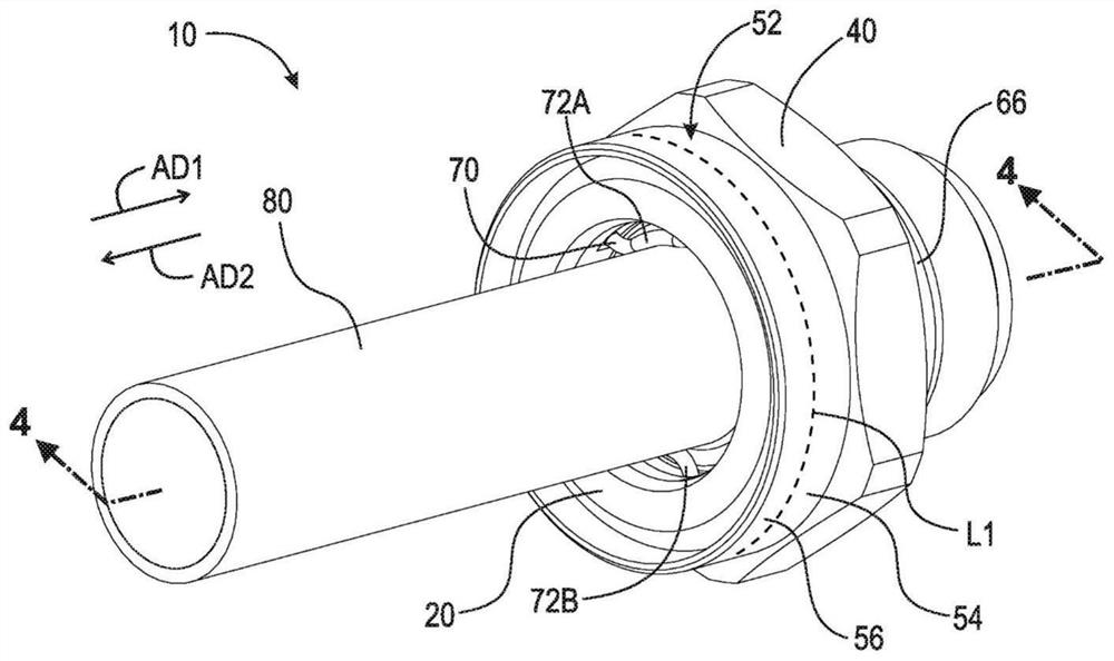
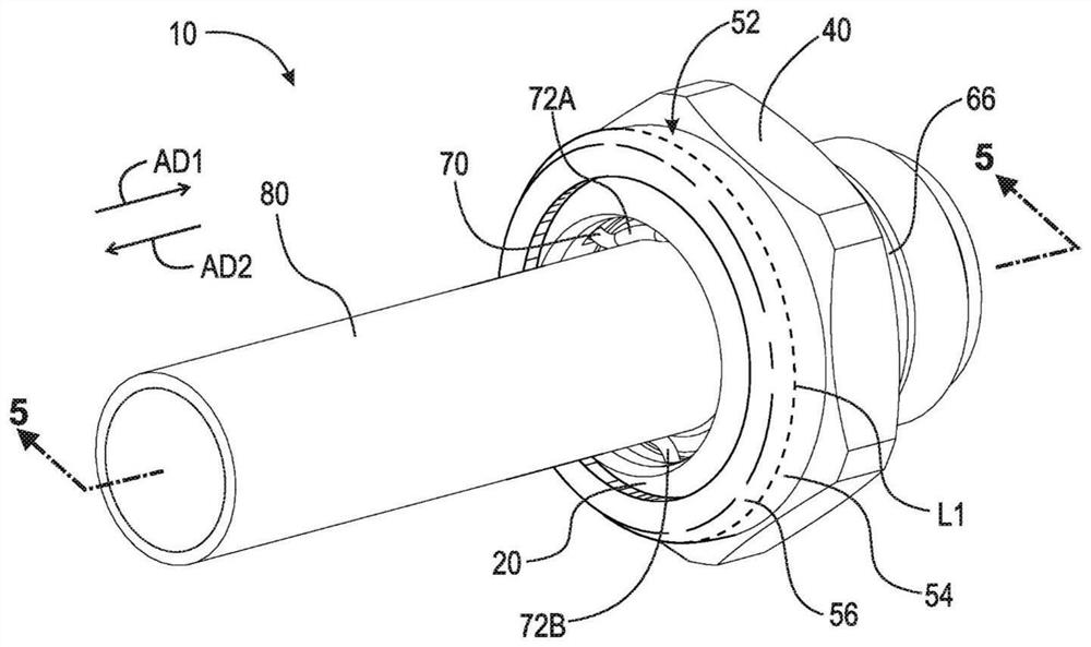
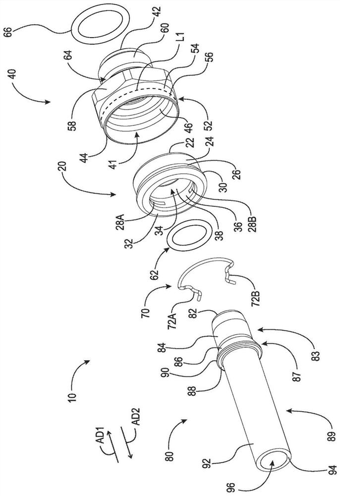
A cartridge (20) for a fluid connector, the fluid connector comprising a connector body (40) having a bore and a flange (52), and a tube end profile (80), the cartridge includes a first end, a second end, a through bore (34), a first radially outward surface (24) including at least one aperture (28A, 28B) extending radially inward into the through bore, and a retention clip (70) including at least one protrusion (72A, 72B) operably arranged to extend into the through bore.

Description

technical field [0001] The present disclosure relates to fluid connectors, and more particularly, to a fluid connector that includes a cartridge for a retaining clip that eliminates the need for post-processing of the connector body and ensures that the retaining clip is always received. Background technique [0002] Fluid connectors are integral components for many applications, especially automotive applications. Because automotive systems are made up of multiple components such as radiators, transmissions, and engines, fluids must be able to flow not only within each component, but also between components. One example of a fluid flowing between components is transmission fluid flowing from the transmission to an oil cooler of the transmission to reduce the temperature of the transmission fluid. Fluid moves between components primarily through flexible or rigid hoses, which are connected to each component by fluid connectors. Such fluid connectors typically include retai...

Claims


Application Information

Patent Timeline
IPC IPC(8): F16L13/16F16L37/088
CPCF16L13/163F16L37/0885F16L37/088
Inventor K.A.扫森K.J.哈根
Owner OTIKER NJ INK
Why Eureka
Try Eureka