
Batch bending forming machine for metal parts

A bending forming and mass production technology, which is applied in metal processing equipment, feeding devices, manufacturing tools, etc., can solve the problems of difficult removal of metal tube clamps, many metal tube clamps, and easy deviation of the position of metal tube clamps, etc. , to achieve the effect of convenient centering and limit

Active Publication Date: 2022-08-05
丰县飞洋金属制品有限公司
View PDF7 Cites 0 Cited by
  • Summary
  • Abstract
  • Description
  • Claims
  • Application Information

AI Technical Summary

Problems solved by technology

[0003] At present, when the metal parts of the tube clamp are formed, the position of the metal tube clamp is prone to deviation, which makes the shape of the metal tube clamp after bending and forming asymmetrical, resulting in the problem that the metal tube clamp cannot be used normally when it is used in the later stage. In the process of batch processing of metal pipe clips, there are often many metal pipe clips stuck in the processing groove after bending, which makes it difficult to remove the metal pipe clips.

Method used


Image

  • Batch bending forming machine for metal parts
  • Batch bending forming machine for metal parts
  • Batch bending forming machine for metal parts

Examples


Embodiment Construction

[0027] Embodiments of the present invention are described in detail below with reference to the accompanying drawings, but the present invention can be implemented in many different ways as defined and covered by the claims.

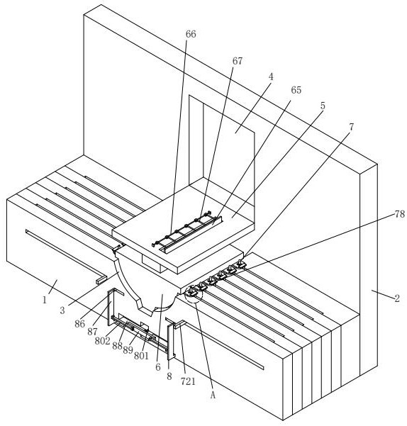
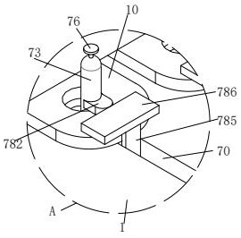
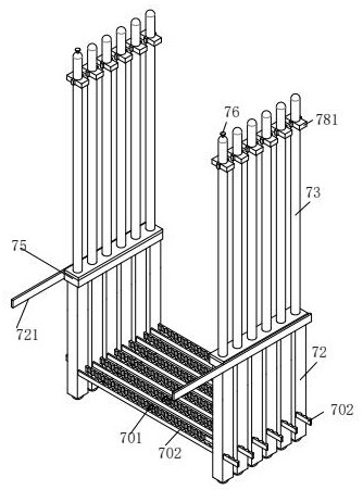
[0028] see figure 1 and Figure 5 , a batch bending and forming machine for metal parts, including a processing table 1, a fixing plate 2 is installed on the rear end surface of the processing table 1, a forming groove 3 is opened on the upper end surface of the processing table 1, and the fixing plate 2 is close to the edge of the processing table 1. The end face is provided with a sliding groove 4 , a lower pressing plate 5 is installed in the sliding groove 4 , a punching head 6 is installed on the lower end surface of the lower pressing plate 5 , and a fixed guiding mechanism 7 is installed on the processing table 1 .

[0029] see figure 1 , figure 2 , image 3 , Figure 5 , Figure 7 , Figure 8 , Figure 9 and Figure 10, the fixed guide ...


PUM


Abstract

The invention relates to the technical field of metal part forming, in particular to a metal part batch bending forming machine which comprises a machining table, and a fixing guide mechanism is installed on the machining table. When the metal pipe clamp is bent, formed and machined, the metal pipe clamp is limited through the fixing guide mechanism, so that the sizes of the metal pipe clamps on the two sides of the forming groove are the same, it is ensured that the shapes of the metal pipe clamps formed through punching are symmetrical, and the situation that the sizes of the two sides of the metal pipe clamp are different in the punching process, and consequently later use cannot be achieved is prevented; and meanwhile, after the forming machining of the metal pipe clamp is completed, the part taking set only needs to pedal a pushing plate to move into a cross-shaped groove, so that a T-shaped pushing plate moves upwards to push out the formed metal pipe clamp upwards, the formed metal pipe clamp is taken out conveniently, and the formed metal pipe clamp is prevented from being clamped in a forming groove.

Description

technical field [0001] The invention relates to the technical field of metal parts forming, in particular to a batch bending forming machine for metal parts. Background technique [0002] The pipe clamp is a kind of metal parts commonly used in plumbing installation. It is used to fix the connection between the pipe and the ground. It has a semicircular or circular structure and is fixed to the wall by screws or nails. The pipe passes through it. When the pipe clamp is made It is to bend the metal strip into a semi-circular structure, and open connecting holes for installing screws or nails at both ends and the middle. [0003] At present, when the metal tube clip metal parts are formed, the position of the metal tube clip is prone to deviation, which makes the shape of the metal tube clip after bending and forming asymmetric, resulting in the problem that the metal tube clip cannot be used normally in the later use. In the process of batch processing of a metal piece tube ...

Claims


Application Information

Patent Timeline
Patent Type & Authority Applications(China)
IPC IPC(8): B21D7/06B21D7/16B21D43/00B21D45/02
CPCB21D7/06B21D7/16B21D43/003B21D45/02
Inventor 杜青锋
Owner 丰县飞洋金属制品有限公司
Learn More