
Triode cooling fin assembling clamp and equipment

A technology for assembling equipment and assembling fixtures

Active Publication Date: 2022-08-05
四川晁禾微电子有限公司
View PDF14 Cites 4 Cited by
  • Summary
  • Abstract
  • Description
  • Claims
  • Application Information

AI Technical Summary

Problems solved by technology

[0003] The heat sink is generally locked on the triode with screws. At present, there are two main ways to assemble the heat sink and the screws. One is to use manual assembly, but the assembly efficiency is low; the other is to use mechanical assembly. For example, the application number is 201510721178 .X's invention patent discloses the "transistor automatic heat sink locking machine" and the invention patent application number 202110682336.0 discloses "a triode and heat sink locking device". Both of the above two patents disclose the use of automated machinery to assemble heat sinks Both solutions can effectively improve the assembly efficiency; however, the structures of the two are relatively complicated, and the problem of positioning the heat sink and the triode cannot be well solved.

Method used


Image

  • Triode cooling fin assembling clamp and equipment
  • Triode cooling fin assembling clamp and equipment
  • Triode cooling fin assembling clamp and equipment

Examples


Embodiment 1

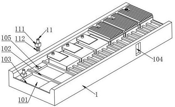
[0038] like figure 1 As shown, a triode heat sink assembly fixture includes: a mounting plate 1 in a rectangular parallelepiped structure.

[0039]Specifically, a plurality of accommodating grooves 101 are arrayed on the top surface of the mounting plate 1 along the length direction for positioning the package body of the triode, so as to realize the rough positioning of the triode. A spacer plate 102 is provided between adjacent accommodating grooves 101 for spacing the triodes in the adjacent accommodating grooves 101, so as to facilitate subsequent assembly of the heat sink. There are end partitions 103 between both end surfaces of the mounting plate 1 in the length direction and the most adjacent accommodating grooves 101, and the thickness of the end partitions 103 is equal to half of the thickness of the partition plates 102, so that the plurality of mounting plates 1 along the length direction When connecting end to end, the distance between the two adjacent accommodat...

Embodiment 2

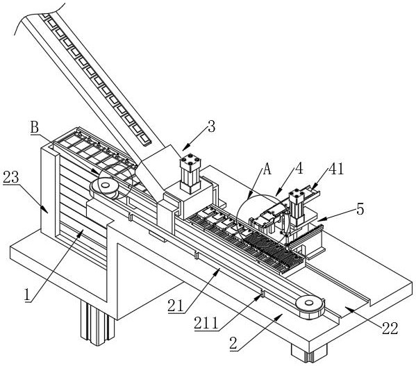
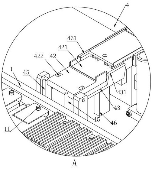
[0044] like figure 2 , Figure 5 and Figure 8 As shown, a triode heat sink assembly equipment includes: a transmission mechanism 2, a feeding mechanism 3, a feeding mechanism 4, a locking mechanism 5, and the triode heat sink assembly fixture of the above-mentioned embodiment 1.

[0045] Specifically, as figure 2 As shown, the feeding mechanism 3, the feeding mechanism 4 and the locking mechanism 5 are arranged in sequence along the conveying direction of the transmission mechanism 2, and the distance between the feeding mechanism 3, the feeding mechanism 4 and the locking mechanism 5 is equal to the distance between the mounting plate 1 n times the distance between the adjacent positioning pins 11, n is an integer.

[0046] Specifically, the feeding mechanism 3 is used to place the triode into the accommodating tank 101 . like figure 2 , Figure 12 As shown, the feeding mechanism 3 includes a feeding tube 31, and the front end of the feeding tube 31 is used to conne...


PUM


Abstract

A triode radiating fin assembling clamp and equipment belong to the technical field of equipment for manufacturing semiconductors, the assembling clamp comprises a mounting plate, and the top surface of the mounting plate is provided with a plurality of accommodating grooves. A positioning pin is arranged at one end of each containing groove and movably arranged in the direction perpendicular to the top face of the mounting plate. Triode cooling fin assembling equipment comprises a conveying mechanism, a feeding mechanism, a feeding mechanism, a locking mechanism and an assembling clamp. The feeding mechanism is used for placing triodes in the containing groove, the feeding mechanism is used for assembling cooling fins to the triodes located in the containing groove, and the locking mechanism is used for assembling the triodes and the cooling fins and locking the connecting screws. The conveying mechanism is used for conveying the mounting plates and simultaneously drives the at least two mounting plates to move. The assembling clamp can improve the assembling and positioning precision of the cooling fins and the triodes, and assembling equipment is simple in structure and high in automation degree.

Description

technical field [0001] The invention belongs to the technical field of equipment for manufacturing semiconductors, and in particular relates to a triode heat sink assembly fixture and equipment. Background technique [0002] Triodes are semiconductor devices commonly used in various electronic products. High-power triodes usually generate a large amount of heat during operation. In order to enhance the heat dissipation speed of such triodes, in the prior art, a heat sink is added on one side of the triode to dissipate heat through The chip dissipates the heat of the triode quickly. [0003] The heat sink is generally locked on the triode with screws. At present, there are two main ways to assemble the heat sink and screws. One is manual assembly, but the assembly efficiency is low; the other is mechanical assembly, for example, the application number is 201510721178 .X's invention patent discloses the "transistor automatic locking heat sink machine" and the invention patent...

Claims


Application Information

Patent Timeline
Patent Type & Authority Applications(China)
IPC IPC(8): B25B11/02
CPCB25B11/02Y02P70/50
Inventor 廖顺才
Owner 四川晁禾微电子有限公司
Learn More