AI technical title is built by PatSnap AI team. It summarizes the technical point description of the patent document.
A door handle and vehicle technology, applied in vehicle locks, vehicle parts, doors, etc., can solve problems such as damage to the visual and auditory texture, collision between door handle rods and switches, etc., to reduce the load and prevent misoperation.
Active Publication Date: 2022-08-05
MAZDA MOTOR CORP
View PDF8 Cites 0 Cited by
Summary
Abstract
Description
Claims
Application Information
AI Technical Summary
This helps you quickly interpret patents by identifying the three key elements:
Problems solved by technology
Method used
Benefits of technology
Problems solved by technology
[0005] However, in the open position of the door handle lever, when the door handle lever is returned to the storage position by the urging force of the above-mentioned spring, there is the following problem when the force is strong. The device makes the door handle bar protrude again
In addition, since the door handle lever is stored at high speed, there is a problem that the door handle lever and the switch collide with each other, so there is a problem that the visual and auditory texture is impaired.
Method used
Image
Click on the blue label to locate the original text in one second.
Reading with bidirectional positioning of images and text.
Examples
Embodiment 1
[0051] An embodiment of the present invention will be described in detail based on the following drawings.
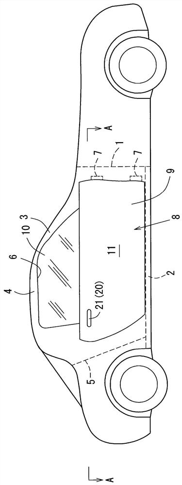
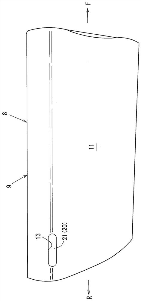
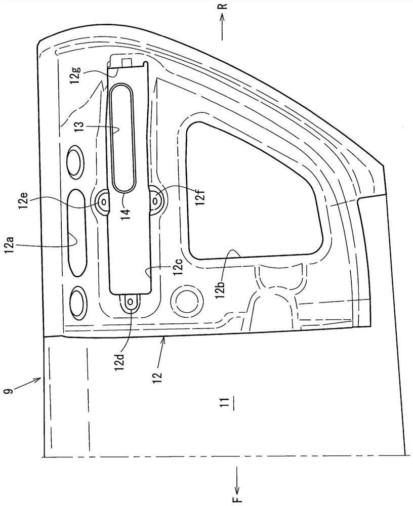
[0052] The accompanying drawing shows the structure of a door handle of a vehicle, figure 1 It is a side view of a vehicle equipped with the door handle structure, figure 2 for figure 1 The main part of the enlarged side view, image 3 An inner side view of the configuration structure for the reinforcement.
[0053] In addition, in the figure, the arrow F represents the front of the vehicle, the arrow R represents the rear of the vehicle, the arrow UP represents the upper side of the vehicle, and the arrow OUT represents the outside in the vehicle width direction.
[0054] In addition, the door handle structure of the vehicle of the present invention can also be applied to the front door, rear door, liftgate, etc. of a 4-door type vehicle.
[0055] like figure 1 As shown, a vehicle having the above door handle structure includes a hinge pillar 1 extending in the v...
Embodiment 2
[0124] Next, refer to Figure 13 to Figure 22 Embodiment 2 of the door handle structure of the vehicle will be described.
[0125] Figure 13 It is a sectional view of the storage state of the handle of Embodiment 2, Figure 14 is the top view of the drive unit, Figure 15 is the top view of the force applying structure involved in the force applying unit, Figure 16 is the top view of the protruding initial position of the handle, Figure 17 is a top view of the grip position of the handle, Figure 18 is a top view of the open position of the handle, Figure 19 Top view of the switch press position for the handle.
[0126] in addition, Figure 20 is the inner side view of the bracket, Figure 21 for the edge Figure 20 Sectional view of line B-B, Figure 22 It is an explanatory diagram of the movement trajectory of the handle, the hinge arm, and the sliding member.
[0127] Furthermore, in Figure 13 to Figure 22 In the drawings, the same symbols are used for the ...
PUM
Abstract
The invention provides a door handle structure of a vehicle, when a handle returns to a storage position, the return speed of the handle is reduced, the load input to a switch in the vehicle of the handle is reduced, the erroneous operation of a driving device is prevented, and the visual texture of an operation state is improved. The hinge device is provided with: a hinge arm (30) having a handle (20) that can be projected from or hidden in a door panel (11) and having a support shaft (31) that rotates the handle in order to project the handle from the door panel; a drive device (40) for transmitting power to the hinge arm in order to project the handle from the door panel; wherein the driving device is provided with a motor (42) and an output shaft (45) which is connected with the hinge arm (30) and transmits the output of the motor to the hinge arm in an area from the storage position to the open position, when the handle (20) moves from the storage position to the holding position, power is transmitted from the motor to the hinge arm through the output shaft, and when the handle (20) moves from the open position to the holding position, power is transmitted from the motor to the hinge arm through the output shaft. Power is transmitted from the hinge arm to the motor through the output shaft.
Description
technical field [0001] The present invention relates to a door handle structure of a vehicle. In the door handle structure of the vehicle, when the door handle bar is stored, the door handle bar forms one side with an outer door panel. Background technique [0002] Conventionally, as disclosed in Patent Document 1, there has been known a door handle structure for a vehicle in which a door handle lever (so-called handle) is stored and has a flush surface structure with an outer door panel on one side. [0003] The door handle structure of a vehicle disclosed in Patent Document 1 is a lever-type door handle structure in which a door handle lever is supported by a shaft extending in the up-down direction, and a spring provided on the shaft supports a door handle lever. A direction urges the said door handle lever, and a convex part provided in the vicinity of the axis|shaft of this handle is operated by an alternation mechanism, and this handle is made to protrude. [0004] In...
Claims
Application Information
Patent Timeline
Application Date:The date an application was filed.
Publication Date:The date a patent or application was officially published.
First Publication Date:The earliest publication date of a patent with the same application number.
Issue Date:Publication date of the patent grant document.
PCT Entry Date:The Entry date of PCT National Phase.
Estimated Expiry Date:The statutory expiry date of a patent right according to the Patent Law, and it is the longest term of protection that the patent right can achieve without the termination of the patent right due to other reasons(Term extension factor has been taken into account ).
Invalid Date:Actual expiry date is based on effective date or publication date of legal transaction data of invalid patent.

