
Transmission, gear shifting fork structure and assembling method of gear shifting fork structure

A shift fork and assembly method technology, applied in the direction of instruments, controlled components, mechanical control devices, etc., can solve the problems of heavy weight, increased cost, and low efficiency

Pending Publication Date: 2022-08-05
HUBEI AVIATION PRECISION MASCH TECH CO LTD
View PDF0 Cites 0 Cited by
  • Summary
  • Abstract
  • Description
  • Claims
  • Application Information

AI Technical Summary

Problems solved by technology

[0003] In the existing transmission, in order to simplify the shift driving form, the lubricating oil inside the transmission is directly used as the hydraulic oil for hydraulic drive, and the shift fork shaft in the shift fork structure is directly used as a piston, so that the hydraulic oil directly acts on the shift fork shaft This requires the shift fork shaft to be of a closed structure, without hydraulic oil leakage. In this structure, the shift fork shaft is usually made of solid steel shaft. Although it can meet the needs of use, it is too heavy to meet the requirements. Automotive Lightweight Requirements
[0004] In order to solve the above problems, currently there are hole structures processed at both ends of the shift fork shaft to achieve the purpose of weight reduction. However, in practical applications, it is found that if the depth of the hole structures at both ends of the shift fork shaft is shallow, the effect of weight reduction is not obvious. If the hole is deep, the processing is difficult and the efficiency is low, resulting in an increase in cost

Method used


Image

  • Transmission, gear shifting fork structure and assembling method of gear shifting fork structure
  • Transmission, gear shifting fork structure and assembling method of gear shifting fork structure
  • Transmission, gear shifting fork structure and assembling method of gear shifting fork structure

Examples


Embodiment Construction

[0037] In order to make those skilled in the art better understand the solution of the present invention, the present invention will be further described in detail below with reference to the accompanying drawings and specific embodiments.

[0038] For ease of understanding and concise description, the following description will be combined with the transmission and its shift fork structure, and the beneficial effects will not be repeated.

[0039] In this embodiment, the transmission includes a synchronizer sleeve, a shift gear and a shift fork structure, and the shift fork structure is used to push the synchronizer sleeve to engage or disengage from the shift gear, thereby realizing the transmission gear. bit change. Among them, the relative positional relationship and action principle of the synchronizer sleeve, the shift gear and the shift fork structure can be referred to the prior art. This paper focuses on improving the shift fork structure. The following focuses on the...


PUM


Abstract

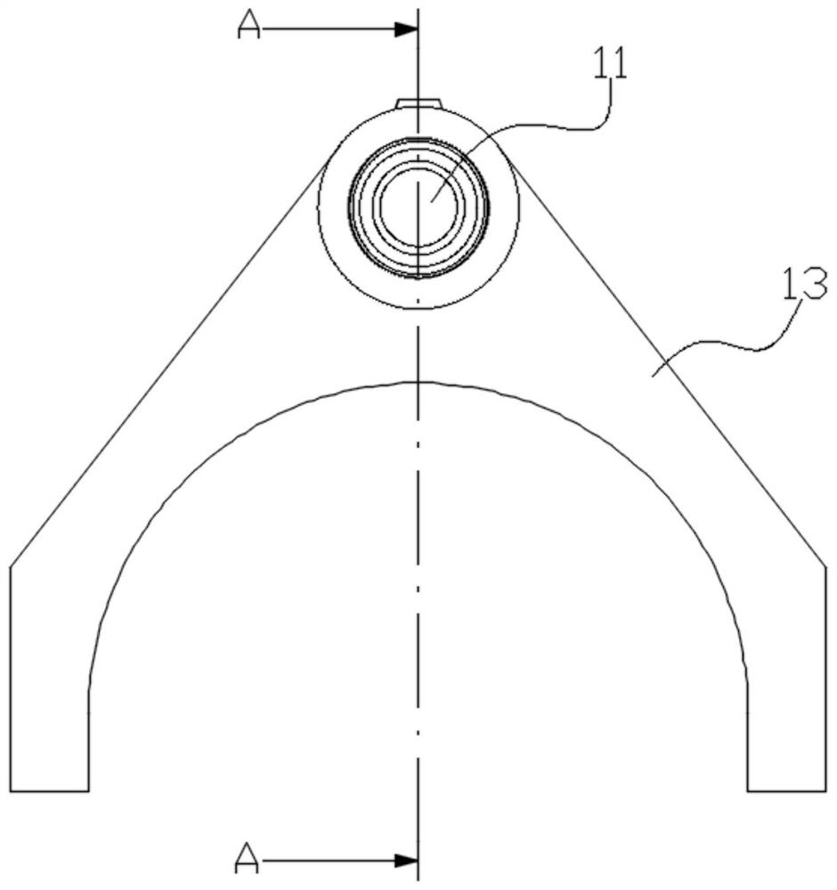
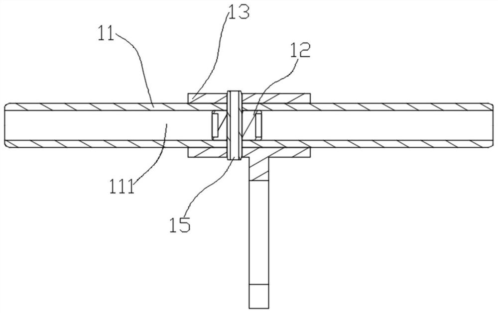
The invention discloses a transmission, a gear shifting fork structure and an assembling method of the gear shifting fork structure. The gear shifting fork structure comprises a shifting fork shaft (11) and a shifting fork body (13), and the shifting fork body (13) is fixed to the shifting fork shaft (11) in a sleeving mode; the gear shifting device further comprises an embedded part (12), the shifting fork shaft (11) is provided with a through hole (111) penetrating through the two ends of the shifting fork shaft (11), and the embedded part (12) is located in the through hole (111) and fixed to the shifting fork shaft (11) in a sealed mode so that the through hole (111) can be divided into two mutually-closed cavities. Through structural optimization of the gear shifting fork structure, the shifting fork shaft of the gear shifting fork structure can meet the functional requirement that the shifting fork shaft is directly driven by hydraulic oil, meanwhile, the weight can be reduced to a large extent, and the development requirement for light weight of automobiles is met.

Description

technical field [0001] The present invention relates to the technical field of transmissions, in particular to a shift fork structure and an assembling method thereof, and also to a transmission including the foregoing shift fork structure. Background technique [0002] In the transmission, the gear change of the transmission is realized by pushing the synchronizer gear sleeve to engage or disengage with the shifting gear through the shifting fork structure. [0003] In the existing transmission, in order to simplify the shift drive form, the lubricating oil inside the transmission is directly used as hydraulic oil for hydraulic drive, and the shift fork shaft in the shift fork structure is directly used as the piston, so that the hydraulic oil directly acts on the shift fork shaft. This requires the fork shaft to be a closed structure and no hydraulic oil leakage can occur. In this structure, the fork shaft usually adopts a solid steel shaft, although it can meet the needs ...

Claims


Application Information

Patent Timeline
IPC IPC(8): F16H63/32
CPCF16H63/32
Inventor 徐俊廖文宗黄智松高惬
Owner HUBEI AVIATION PRECISION MASCH TECH CO LTD
Learn More