Optical projection equipment

An optical projection and equipment technology, applied in optics, instruments, projection devices, etc., can solve the problems of large number of glues, cumbersome dispensing process, incomplete glue curing, etc., to solve the problem of incomplete curing and reduce the number of glues. Effect

Pending Publication Date: 2022-08-05
GOERTEK OPTICAL TECH CO LTD
View PDF0 Cites 0 Cited by
  • Summary
  • Abstract
  • Description
  • Claims
  • Application Information

AI Technical Summary

Problems solved by technology

[0004] It can be seen that the current method of dispensing glue between the lens and the side wall of the optical chassis will result in a large amount of dispensing, a cumbersome dispensing process, and the risk of incomplete curing and volatile glue.

Method used


Image

  • Optical projection equipment
  • Optical projection equipment
  • Optical projection equipment

Examples


Embodiment Construction

[0029] Various exemplary embodiments of the present application will now be described in detail with reference to the accompanying drawings. It should be noted that the relative arrangement of the components and steps, the numerical expressions and numerical values ​​set forth in these embodiments do not limit the scope of the present application unless specifically stated otherwise.

[0030] The following description of at least one exemplary embodiment is merely illustrative in nature and is in no way intended to limit the application, its application, or uses.

[0031] Techniques and devices known to those of ordinary skill in the relevant art may not be discussed in detail, but where appropriate, such techniques and devices should be considered part of the specification.

[0032] In all examples shown and discussed herein, any specific value should be construed as illustrative only and not as limiting. Accordingly, other instances of the exemplary embodiment may have diff...


PUM


Abstract

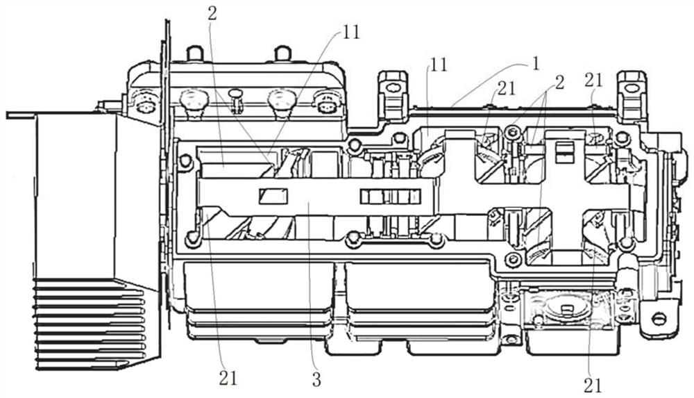
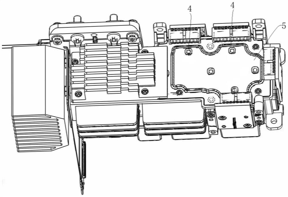
The invention discloses optical projection equipment. The optical projection equipment comprises an optical machine shell and a cover plate, a containing cavity is formed in the optical machine shell, and the cover plate is used for covering the containing cavity; the lens group comprises a plurality of lenses, and the lenses are positioned in the accommodating cavity; the lens group is provided with a containing cavity, the cover plate covers the containing cavity, the connecting piece is arranged between the lens group and the cover plate, and under the condition that the cover plate covers the containing cavity, the surface, away from the cover plate, of the connecting piece abuts against the upper end face of each lens in the lens group or adheres to the upper end face of each lens in the lens group.

Description

technical field [0001] The present application relates to the technical field of optical devices, and more particularly, to an optical projection device. Background technique [0002] Digital Light Processing (DLP) projector display mode has the characteristics of high brightness, high contrast and high resolution. Combined with LED light source, it can realize miniaturized portable micro-projection, which is welcomed by more and more users. . [0003] In the prior art, glue is dispensed between the lens and the side wall of the optical cabinet, so that the lens is fixed in the optical cabinet. In order to realize the fixation of the lens, at least two dispensing positions are formed between the lens and the side wall of the optical housing, and the dispensing equipment is used to dispense glue at the corresponding dispensing positions one by one. [0004] It can be seen that the current method of dispensing glue between the lens and the side wall of the optical housing wi...

Claims


Application Information

Patent Timeline
Patent Type & Authority Applications(China)
IPC IPC(8): G03B21/14
CPCG03B21/142G03B21/145
Inventor 姜泓杉陈华斌
Owner GOERTEK OPTICAL TECH CO LTD
Why Eureka
Try Eureka