Protection device for electronic information equipment
An electronic information and protection device technology, applied in mechanical equipment, transportation and packaging, chassis/boxes/drawer parts, etc., can solve problems such as poor protection effect, and achieve the effect of not easy to damage and good protection effect.
- Summary
- Abstract
- Description
- Claims
- Application Information
AI Technical Summary
Problems solved by technology
Method used
Image
Examples
Embodiment 1
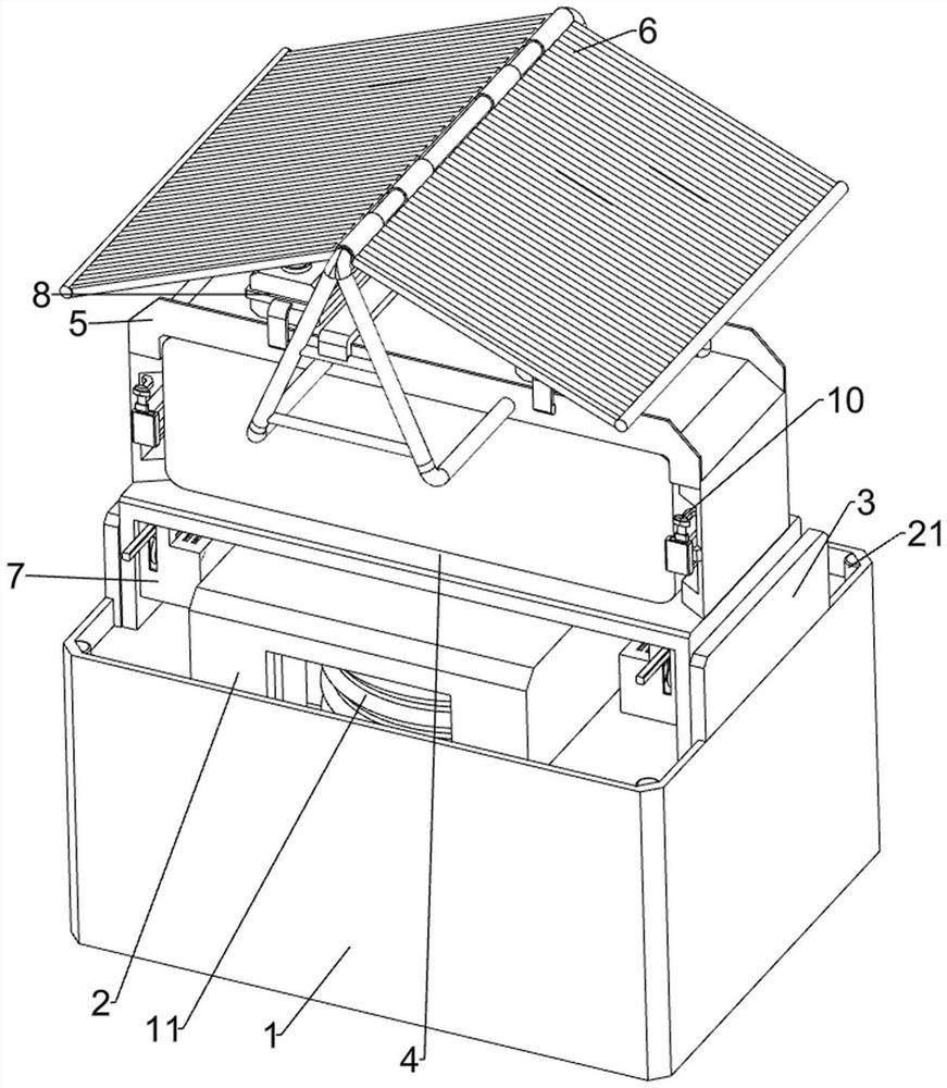
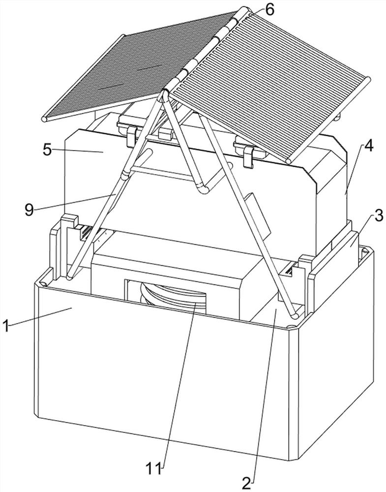
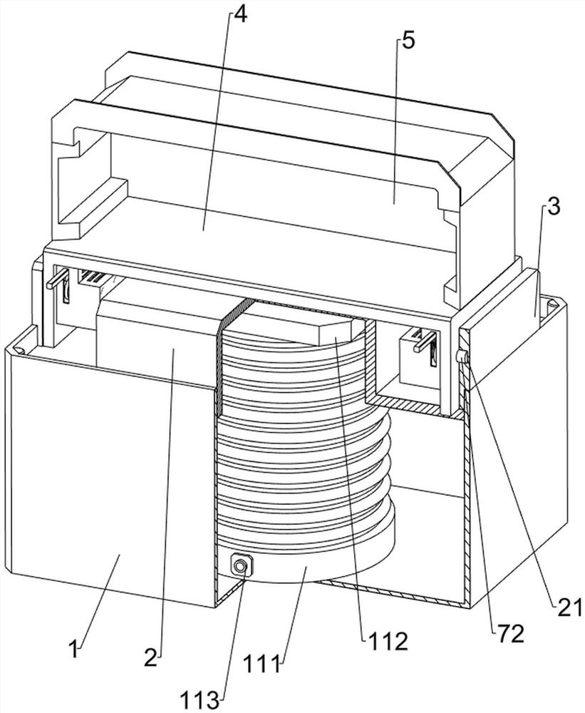
[0035] A protection device for electronic information equipment, please see figure 1 , figure 2 , image 3 , Figure 4 , Figure 5 , Figure 8 , Figure 9 , Figure 10 , Figure 13 and Figure 14 , including a protective box 1, a support frame 2, an anti-skid strip 21, a first connecting plate 3, a U-shaped frame 4, a protective frame 5, a protective mechanism 6, a clamping mechanism 7 and a pulling mechanism 9. The bottom of the protective box 1 is provided with The anti-skid pad enables the protective box 1 to be stably placed on the ground. The inner side wall of the protective box 1 is connected with four anti-skid strips 21 at even intervals. The left and right sides of the top of the protective box 1 are connected with the first connecting plate 3 by welding. , a support frame 2 is slidably connected between the four anti-skid strips 21, the support frame 2 is slidably connected with the protective box 1, the support frame 2 is connected with a U-shaped frame 4 ...
Embodiment 2
[0041] On the basis of Example 1, please see figure 1 , Figure 11 and Figure 12 , also includes a heat dissipation mechanism 8, the heat dissipation mechanism 8 includes a water storage tank 81, a water pipe 82, a water collecting frame 83 and a spray head 85, two guide plates are evenly spaced with water diversion grooves 84, the upper part of the protective frame 5 is symmetrical There are two water storage tanks 81 connected in a way, the bottoms of the two water storage tanks 81 are installed with nozzles 85, and the separated sides of the two protective plates 62 are connected with a water collecting frame 83 by welding, and the two water collecting frames 83 are connected with the phase A water pipe 82 is connected between the adjacent water storage tanks 81. By starting the sprinkler head 85, the sprinkler head 85 will spray the rainwater in the water collecting frame 83 on the protective frame 5, so that the rainwater will pass through the protective frame 5 to heat...
Embodiment 3
[0044] On the basis of Example 2, please see figure 1 , Image 6 and Figure 7 , also includes a push mechanism 10, the push mechanism 10 includes a guide rod 101, a sliding plate 102, a sliding frame 103, a guide 104, a limiter 105 and a third spring 106, and the left and right sides of the protective frame 5 are connected with guides Rod 101, a sliding plate 102 is slidably connected between the two guide rods 101, two third springs 106 are connected between the sliding plate 102 and the protective frame 5, and two sliding frames 103 are symmetrically connected to the front side wall of the sliding plate 102. , the front sides of the left and right side walls inside the protective frame 5 are connected with guide pieces 104 by welding, the two guide pieces 104 are located on the upper side of the adjacent sliding frame 103, and the front sides of the two guide pieces 104 are both slidably penetrating limited The positioning member 105, the two limiting members 105 are in c...
PUM
 Abstract
Description
Claims
Application Information
 - R&D
- Intellectual Property
- Life Sciences
- Materials
- Tech Scout
- Unparalleled Data Quality
- Higher Quality Content
- 60% Fewer Hallucinations
Browse by: Latest US Patents, China's latest patents, Technical Efficacy Thesaurus, Application Domain, Technology Topic, Popular Technical Reports.
© 2025 PatSnap. All rights reserved.Legal|Privacy policy|Modern Slavery Act Transparency Statement|Sitemap|About US| Contact US: help@patsnap.com


