Insulation fixing device for electronic component
A technology of electronic components and fixing devices, which is applied in general water supply saving, cabinet/cabinet/drawer components, cooling/ventilation/heating transformation, etc., which can solve the problem of easily damaged parts and small parts that are difficult to take out and replace The process is cumbersome and other problems, to achieve the effect of preventing dust from entering and accelerating the speed of movement
- Summary
- Abstract
- Description
- Claims
- Application Information
AI Technical Summary
Problems solved by technology
Method used
Image

Examples
Embodiment 1
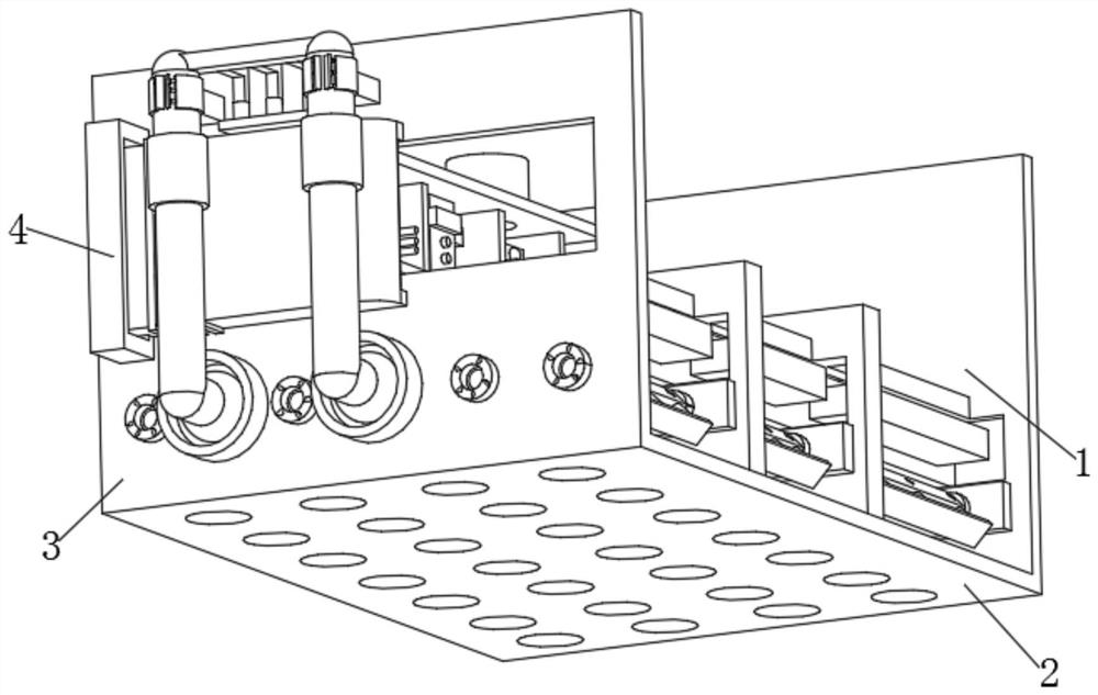
[0033] Example one, as Figure 1-Figure 2 As shown, the present invention provides a technical solution: specifically including:
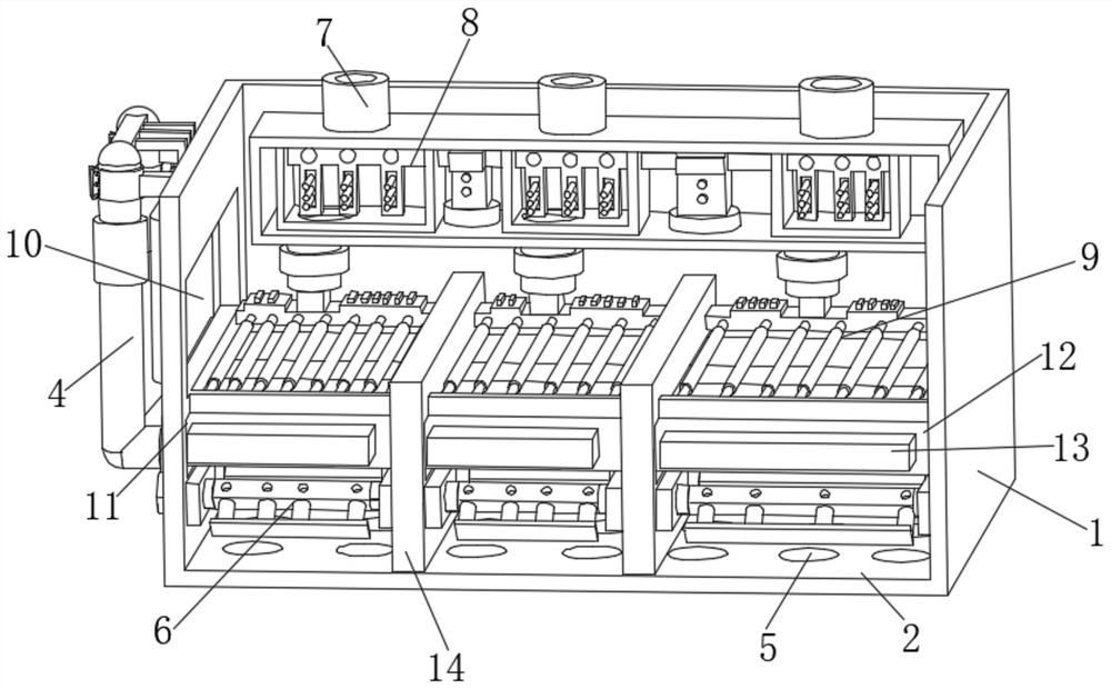
[0034]Fixed box 1, the fixed box 1 has a stable base, and a filter screen bottom plate 2 arranged at the bottom of the fixed box 1, the outside of the fixed box 1 is fixedly connected with a reinforced outer plate 3, and the bottom of the inside of the fixed box 1 is provided with a circular hole 5, A water inlet filter 7 is arranged above the interior of the fixed box 1 , a cooling treatment mechanism 8 is fixedly connected below the water inlet filter 7 , a cooling mechanism 9 is fixedly connected below the cooling treatment mechanism 8 , and the middle of the reinforcement outer plate 3 is provided with flow port 10;
[0035] The control mechanism 4, the control mechanism 4 has a thickened casing, and a ventilation mechanism 6 arranged inside the control mechanism 4, the right side of the ventilation mechanism 6 is provided with a placement slo...
Embodiment 2
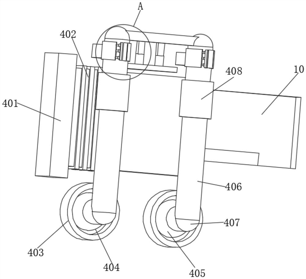
[0037] Example two, as image 3 As shown, a collection box 401 is arranged inside the control mechanism 4, a telescopic sliding door 402 is arranged inside the collection box 401, a fixed outer ring 403 is arranged below the inside of the control mechanism 4, and a first recess is arranged inside the fixed outer ring 403 In the groove 404, a reinforcement base 405 is fixedly connected to the inside of the first groove 404, and a support rotating column 406 is fixedly connected to the front of the strengthening base 405. The adjusting button 408 is fixedly connected with the adjusting mechanism A above the supporting rotating column 406 .
[0038] The circular hole 5 communicates with the screen bottom plate 2 , the telescopic sliding door 402 is arranged outside the flow port 10 , the collecting box 401 is arranged outside the reinforced outer plate 3 , and the fixed outer ring 403 is fixedly connected to the outside of the reinforced outer plate 3 . Has the advantage of bein...
Embodiment 3
[0039] Example three, as Figure 4 As shown, the ventilation mechanism 6 includes an air intake fan 601, the interior of the air intake fan 601 is provided with a filter screen 602, the interior of the ventilation mechanism 6 is fixedly connected with a reinforcing partition 603, and the left side of the reinforcing partition 603 is fixedly connected with a fixing ring 604 , a ventilation pipe 605 is fixedly connected to the middle of the fixing ring 604 , and a ventilation hole 606 is opened above the ventilation pipe 605 .
[0040] A connecting column 607 is fixedly connected to the outside of the ventilation pipe 605 , and an adsorption plate 608 is fixedly connected to the bottom of the connecting column 607 . It has the advantages of assisting the heat dissipation of electronic components and adsorbing impurities and dust. The air enters the internal filter screen from the position of the air inlet fan, and the impurities are filtered and cannot enter the fixed box. The ...
PUM
 Abstract
Description
Claims
Application Information
 - Generate Ideas
- Intellectual Property
- Life Sciences
- Materials
- Tech Scout
- Unparalleled Data Quality
- Higher Quality Content
- 60% Fewer Hallucinations
Browse by: Latest US Patents, China's latest patents, Technical Efficacy Thesaurus, Application Domain, Technology Topic, Popular Technical Reports.
© 2025 PatSnap. All rights reserved.Legal|Privacy policy|Modern Slavery Act Transparency Statement|Sitemap|About US| Contact US: help@patsnap.com