
Cable tube winding equipment and winding process

A cable tube and equipment technology, applied in the field of cable tube winding equipment and winding technology, can solve the problems of easy dripping of glue, low work efficiency, and difficulty in cleaning, so as to avoid troublesome cleaning, improve work efficiency, and reduce occupation The effect of the area

Active Publication Date: 2022-08-09
常州九洲创胜特种铜业有限公司
View PDF5 Cites 0 Cited by
  • Summary
  • Abstract
  • Description
  • Claims
  • Application Information

AI Technical Summary

Problems solved by technology

[0003] In the prior art, the winding speed of the cable tube is accelerated by setting two winders; however, when the cable tube is wound, it is necessary to manually apply glue to the outer wall of the glass fiber. This method is not only complicated to operate, but also low in work efficiency; and the level of The glue coated on the outer wall of the placed cable tube is easy to drip down, which not only wastes the glue, but also makes it difficult to clean up after the glue is cured

Method used


Image

  • Cable tube winding equipment and winding process
  • Cable tube winding equipment and winding process
  • Cable tube winding equipment and winding process

Examples


Embodiment 1

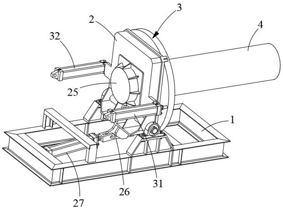
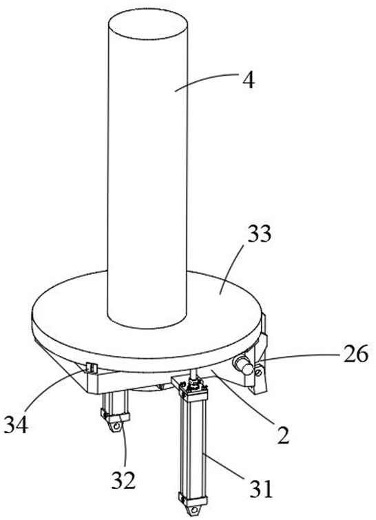
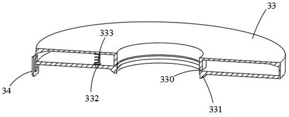
[0050] like Figure 1 to Figure 6As shown, the present invention provides a cable tube winding device, including a fixing frame 1, a base 2, a gluing part 3 and a support column 4, the base 2 is hinged on the upper end of the fixing frame 1; push the base 2 , the base 2 can be rotated axially with the hinge point as the axis, so that the base 2 is in a vertical or horizontal state; the support column 4 is rotatably arranged on the base 2, and the support column 4 The length of the cable tube is not less than the length of the cable tube to be processed, so that when gluing the outer wall of the cable tube and winding the fiberglass, the support column 4 can support and fix the cable tube; meanwhile, the support column 4 is provided with a heating resistance wire inside, In this way, when the glue is coated on the outer wall of the cable tube, the support column 4 continues to heat the cable tube, which can effectively prolong the curing time of the glue. The gluing part 3 is ...

Embodiment 2

[0058] On the basis of the first embodiment, the second embodiment also provides a winding process for a circuit tube winding device, including the circuit tube winding device described in the first embodiment. The specific structure is the same as that of the first embodiment. Without further elaboration, a specific winding process of a circuit tube winding device is as follows:

[0059] After the cable tube is sleeved on the outer wall of the support column 4 and one end is in contact with the base 2, the cylinder 27 is pushed to drive the base 2 to rotate 90° with the hinge point as the axis, so that the support column 4 is in a vertical state; the first driving cylinder 31 and The second driving cylinder 32 synchronously drives the glue storage bin 33 from both sides of the glue storage bin 33 to move upward along the axial direction of the support column 4 , so that the glue in the glue storage bin 33 flows from the glue outlet 330 to the cable tube The outer wall is coat...


PUM


Abstract

The invention relates to the technical field of winding machines, in particular to cable tube winding equipment and a winding process. According to the cable pipe winding equipment, a supporting column is rotatably arranged on a base, and the supporting column is suitable for fixing a cable pipe; the glue storage bin is hollow; during working, the base is driven to axially rotate by taking a hinge point as an axis until the supporting column is in a vertical state; the first driving air cylinder and the second driving air cylinder synchronously drive the glue storage bin to move upwards in the axial direction of the supporting column from the two sides of the glue storage bin so that the outer wall of the cable pipe can be glued. The supporting column is rotated, and the glue storage bin drives the concentrator to synchronously move upwards, so that the glass fiber reinforced plastic fibers are wound on the outer wall of the cable pipe; and after winding is finished, the glue storage bin moves downwards and scrapes redundant glue on the outer wall of the cable pipe, so that the redundant glue drops on the base to be recycled. And through cooperation of the gluing part and the base, the effect of collecting redundant glue after gluing is achieved, and meanwhile the working efficiency of gluing is improved.

Description

technical field [0001] The invention relates to the technical field of winding machines, in particular to a cable tube winding device and a winding process. Background technique [0002] Application number: CN201920264062.1, publication (announcement) number: CN209940118U, a double-reel winding machine for cable tube manufacturing, the utility model discloses a cable tube manufacturing double-reel winding machine, the structure of which includes a body, a base, and a bearing , Left winder, pillar, right winder, the body is provided with a base, the base is fixedly connected with the body, the base is provided with a support, the support is provided with a bearing, and the bearing is connected to the support Fixed connection, the left side of the strut is provided with a left winder, the right side of the left winder is provided with a right winder, the left winder and the right winder are provided with a rotating shaft, the rotating shaft The winder is disassembled and conn...

Claims


Application Information

Patent Timeline
Patent Type & Authority Applications(China)
IPC IPC(8): B29C53/60B29C53/80
CPCB29C53/60B29C53/8008
Inventor 张锋清杨玉成范卫庆
Owner 常州九洲创胜特种铜业有限公司
Learn More