Automatic control system for left and right tracks to travel synchronously

An automatic control system and crawler technology, which is applied in the direction of control drive, crawler vehicles, motor vehicles, etc., can solve the problems that cannot meet the requirements of use, cannot achieve synchronization, and the size of manual control force is different, so as to reduce the intensity of manual operation and improve the response. Sensitive, highly automated results

Active Publication Date: 2015-07-01
CHINA RAILWAY CONSTR HEAVY IND
View PDF5 Cites 6 Cited by
  • Summary
  • Abstract
  • Description
  • Claims
  • Application Information

AI Technical Summary

Problems solved by technology

However, the applicant of the present invention has found that this control system in the prior art has the following disadvantages: due to the unequal magnitude of manual control force, the purpose of synchronization cannot be achieved, although the prior art still uses an angle encoder to measure the left and right The deflection angle of the beam is adjusted by calculating the difference between the left and right walks to make up for the lack of manual adjustment. However, it is finally realized through the manual operation of the operator. Obviously, the manual operation mode requires equipment with high straightness requirements. The control method obviously cannot meet the requirements of use

Method used


Image

  • Automatic control system for left and right tracks to travel synchronously
  • Automatic control system for left and right tracks to travel synchronously
  • Automatic control system for left and right tracks to travel synchronously

Examples


specific Embodiment 1

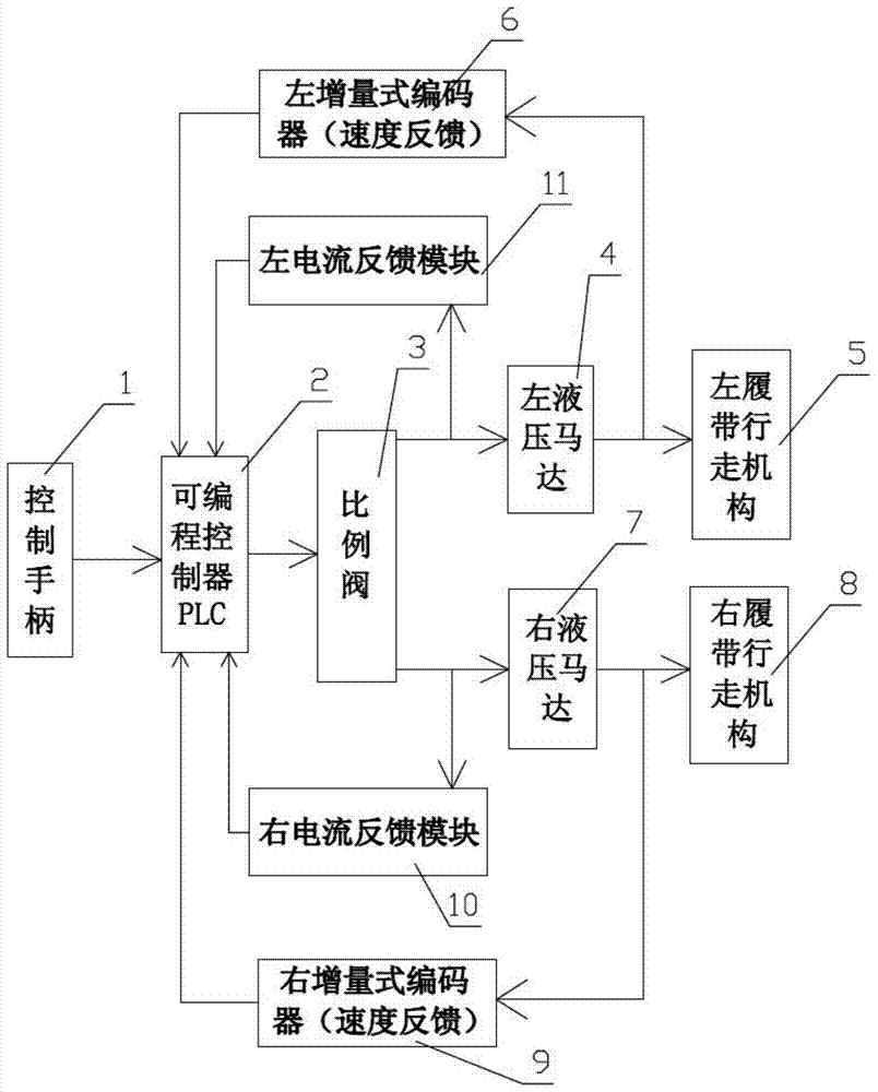
[0016] combined with figure 2 And attached image 3 , an automatic control system for synchronous walking of the left and right crawlers, which includes a control handle 1, a programmable logic controller PLC 2, a proportional valve 3, a left hydraulic motor 4, a left crawler mechanism 5, a left incremental encoder 6, a right Hydraulic motor 7, right crawler walking mechanism 8, right incremental encoder 9, right current feedback module 10 and left current feedback module 11; control handle 1 is electrically connected to programmable controller PLC2; control signal of programmable controller PLC2 The output end is electrically connected to the signal input end of the proportional valve 3; the hydraulic output end of the proportional valve 3 is divided into two circuits, one is connected with the left hydraulic motor 4 and the left crawler running mechanism 5 in turn, and the other is connected with the right hydraulic motor 7 and the right crawler in turn The walking mechani...

specific Embodiment 2

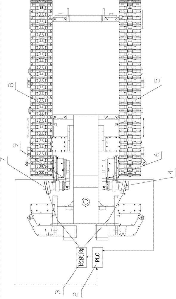
[0017] further combined with Figure 4 , an automatic control system for synchronous walking of the left and right crawlers, which includes a control handle 1, a programmable logic controller PLC 2, a proportional valve 3, a left hydraulic motor 4, a left crawler mechanism 5, a left incremental encoder 6, a right Hydraulic motor 7, right crawler walking mechanism 8, right incremental encoder 9, right current feedback module 10 and left current feedback module 11; control handle 1 is electrically connected to programmable controller PLC2; control signal of programmable controller PLC2 The output end is electrically connected to the signal input end of the proportional valve 3; the hydraulic output end of the proportional valve 3 is divided into two circuits, one is connected with the left hydraulic motor 4 and the left crawler running mechanism 5 in turn, and the other is connected with the right hydraulic motor 7 and the right crawler in turn The walking mechanism 8 is connect...


PUM


Abstract

The invention discloses an automatic control system for left and right tracks to travel synchronously better suitable for equipment having relatively high requirement on straightness during traveling. The automatic control system comprises a control handle, a programmable controller PLC, a proportional valve, a left hydraulic motor, a left track traveling mechanism, a left incremental encoder, a right hydraulic motor, a right track traveling mechanism and a right incremental encoder; the control handle is electrically connected with the programmable controller PLC; the programmable controller PLC is electrically connected with the proportional valve; the output end of the proportional valve is divided into two branches, and one branch is orderly connected with the left hydraulic motor and the left track traveling mechanism, while the other branch is orderly connected with the right hydraulic motor and the right track traveling mechanism; the signal output end of the left hydraulic motor is electrically connected with the programmable controller PLC by use of the left incremental encoder; the signal output end of the right hydraulic motor is electrically connected with the programmable controller PLC by use of the right incremental encoder; the proportional valve is electrically connected with the programmable controller PLC by use of two branches of currents simultaneously.

Description

technical field [0001] The invention relates to a mechanical control system, in particular to an automatic control system for synchronous walking of left and right crawler belts in a crawler belt traveling mechanism. Background technique [0002] At present, the crawler traveling mechanism is widely used on large-scale mechanical equipment, especially heavy-duty mechanical equipment in railway construction, such as bolter, etc. Most of these equipment use two crawlers on the left and right to realize walking. There is no special requirement for the synchronous walking of the left and right crawlers, and the operator maintains the straight running of the left and right crawlers by manually adjusting the control handle. further combined with figure 1 , the control system for synchronous walking of the left and right crawlers in the prior art includes a left control handle 01, a left hydraulic motor 02, a left crawler traveling mechanism 03, a right control handle 04, a right ...

Claims


Application Information

Patent Timeline
Patent Type & Authority Applications(China)
IPC IPC(8): B62D55/08B60L15/00
CPCB62D11/003B62D11/005Y02T10/64
Inventor 袁长锁刘在政麻成标刘金书吴涛邹黎勇
Owner CHINA RAILWAY CONSTR HEAVY IND
Why Eureka
Try Eureka