Control system for flue gas oxygen content of layer combustion boiler based on flue gas recirculation

A technology of flue gas recirculation and boiler flue gas, which is applied in the direction of controlled combustion, solid fuel combustion, and combustion methods. The effect of large load variation range, reduction of initial emission concentration, and reduction of manual operation intensity

Active Publication Date: 2017-09-15
廊坊市华源盛世热力有限公司
View PDF5 Cites 6 Cited by
  • Summary
  • Abstract
  • Description
  • Claims
  • Application Information

AI Technical Summary

Problems solved by technology

[0003] However, my country's floor-fired boilers are characterized by a large number, small single capacity, low thermal efficiency, and large load changes. In particular, industrial boilers shared by production and heating are basically selected according to the maximum load demand in the heating season, resulting in non-heating During the season (after heating off) it operates under lower load for a long time
The traditional oxygen control system of the floor-fired boiler is only regulated and controlled through the inlet baffle of the boiler blower fan. However, in order to ensure that the horizontal air distribution of the grate is uniform and maintain a certain penetration under the low-load operation of the boiler, the air supply pressure must be maintained. Above the minimum wind pressure, coupled with the large air leakage and blowing wind in the air chamber, the oxygen content in the flue gas is as high as 15% (the excess air coefficient is 3.5), which increases the amount of flue gas, and because the boiler operates at low load , the flue gas flow rate is low, the heated area of ​​the convection tube bundle, economizer, air preheater, etc. is seriously dusty, the boiler exhaust temperature rises, and the boiler exhaust heat loss is relatively large, which not only increases the fuel cost of the enterprise, but also wastes coal resource
At the same time, due to the serious excess of oxygen in the furnace, the concentration of nitrogen oxides produced by coal combustion is high, which increases the environmental protection operation cost of the enterprise

Method used


Image

  • Control system for flue gas oxygen content of layer combustion boiler based on flue gas recirculation
  • Control system for flue gas oxygen content of layer combustion boiler based on flue gas recirculation

Examples


Embodiment 1

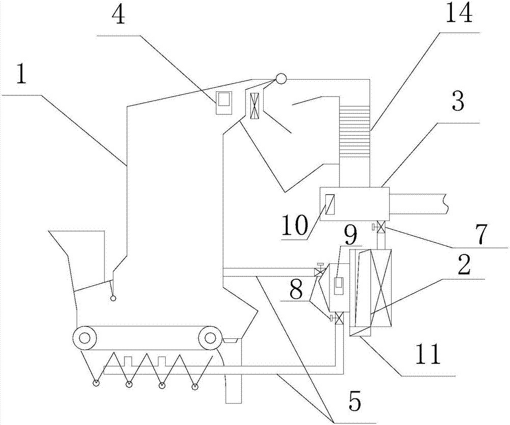
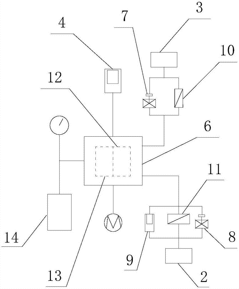
[0024] Such as Figure 1 to Figure 2 As shown, a layer-fired boiler flue gas oxygen content control system based on flue gas recirculation is mainly composed of a layer-fired boiler 1, a blower 2, a flue gas recirculation fan 3, a zirconia analyzer 4, an air duct 5 and a DCS The system (or PLC system) consists of 6, the furnace of the layer-fired boiler 1 is connected with the blower 2 through the air duct 5, the smoke outlet of the layer-fired boiler 1 is installed with a zirconia analyzer 4, and the smoke outlet of the layer-fired boiler 1 A flue gas recirculation fan 3 is arranged on the channel, and the flue gas recirculation fan 3 is connected to the air inlet of the blower 2 through the air pipe 5, and the flue gas recirculation fan 3 is connected with a first fan frequency conversion controller 10 and an electric regulating valve 7 , the electric regulating valve one 7 is installed on the air pipe 5 connecting the flue gas recirculation fan 3 to the air inlet of the blo...

Embodiment 2

[0026] Such as Figure 1 to Figure 2 As shown, a layer-fired boiler flue gas oxygen content control system based on flue gas recirculation is mainly composed of a layer-fired boiler 1, a blower 2, a flue gas recirculation fan 3, a zirconia analyzer 4, an air duct 5 and a DCS The system (or PLC system) consists of 6, the furnace of the layer-fired boiler 1 is connected with the blower 2 through the air duct 5, the smoke outlet of the layer-fired boiler 1 is installed with a zirconia analyzer 4, and the smoke outlet of the layer-fired boiler 1 A flue gas recirculation fan 3 is arranged on the channel, and the flue gas recirculation fan 3 is connected to the air inlet of the blower 2 through the air pipe 5, and the flue gas recirculation fan 3 is connected with a first fan frequency conversion controller 10 and an electric regulating valve 7 , the electric regulating valve one 7 is installed on the air pipe 5 connecting the flue gas recirculation fan 3 to the air inlet of the blo...

Embodiment 3

[0029] Such as Figure 1 to Figure 2 As shown, a layer-fired boiler flue gas oxygen content control system based on flue gas recirculation is mainly composed of a layer-fired boiler 1, a blower 2, a flue gas recirculation fan 3, a zirconia analyzer 4, an air duct 5 and a DCS The system (or PLC system) consists of 6, the furnace of the layer-fired boiler 1 is connected with the blower 2 through the air duct 5, the smoke outlet of the layer-fired boiler 1 is installed with a zirconia analyzer 4, and the smoke outlet of the layer-fired boiler 1 A flue gas recirculation fan 3 is arranged on the channel, and the flue gas recirculation fan 3 is connected to the air inlet of the blower 2 through the air pipe 5, and the flue gas recirculation fan 3 is connected with a first fan frequency conversion controller 10 and an electric regulating valve 7 , the electric regulating valve one 7 is installed on the air pipe 5 connecting the flue gas recirculation fan 3 to the air inlet of the blo...


PUM


Abstract

The invention provides a control system for the flue gas oxygen content of a layer combustion boiler based on flue gas recirculation. The control system is mainly composed of the layer combustion boiler, a blower, a flue gas recirculation fan, a zirconium oxide analyzer, an air pipe, a DCS system (or a PLC system) and the like, and can be widely applied to the field of combustion control and combustion optimization of layer combustion boilers. The control system adopts conventional equipment, performance is reliable and stable, stable operation of the boiler under the very low load (the 30% rated load) can be achieved, ash accumulating of the heating surface of the tail of the boiler is reduced, the initial discharge concentration of boiler nitrogen and oxygen compounds can be reduced by 15-20%, and the heat efficiency of the boiler under the low load is improved by 5% or more.

Description

technical field [0001] The invention belongs to the technical field of floor-fired boilers, in particular to a system for controlling the oxygen content of floor-fired boiler flue gas based on flue gas recirculation. Background technique [0002] Industrial boilers are important thermal power equipment, accounting for more than 98% of the total boilers in my country. Among the coal-fired industrial boilers, the floor-fired furnace accounts for about 80% of the total capacity, and plays an indispensable role in the development of the national economy and the lives of residents. [0003] However, my country's floor-fired boilers are characterized by a large number, small single capacity, low thermal efficiency, and large load changes. In particular, industrial boilers shared by production and heating are basically selected according to the maximum load demand in the heating season, resulting in non-heating During the season (after the heating is turned off), it operates under ...

Claims


Application Information

Patent Timeline
Patent Type & Authority Applications(China)
IPC IPC(8): F23N3/06F23B80/02
CPCF23B80/02F23N3/06F23N2221/12F23N2239/02
Inventor 范向军罗凯白东生王玉国王兴钦刘有均李洪元
Owner 廊坊市华源盛世热力有限公司
Why Eureka
Try Eureka