
Piston for IC engine

A technology for internal combustion engines and pistons, which is applied in the field of internal combustion engine pistons, and can solve problems such as reducing the knocking sound of pistons

Inactive Publication Date: 2004-06-16
HONDA MOTOR CO LTD
View PDF1 Cites 0 Cited by
  • Summary
  • Abstract
  • Description
  • Claims
  • Application Information

AI Technical Summary

Problems solved by technology

This doesn't help reduce piston smack

Method used


Image

  • Piston for IC engine
  • Piston for IC engine
  • Piston for IC engine

Examples


Embodiment Construction

[0028] Now, the present invention will be described by means of embodiments with reference to the accompanying drawings.

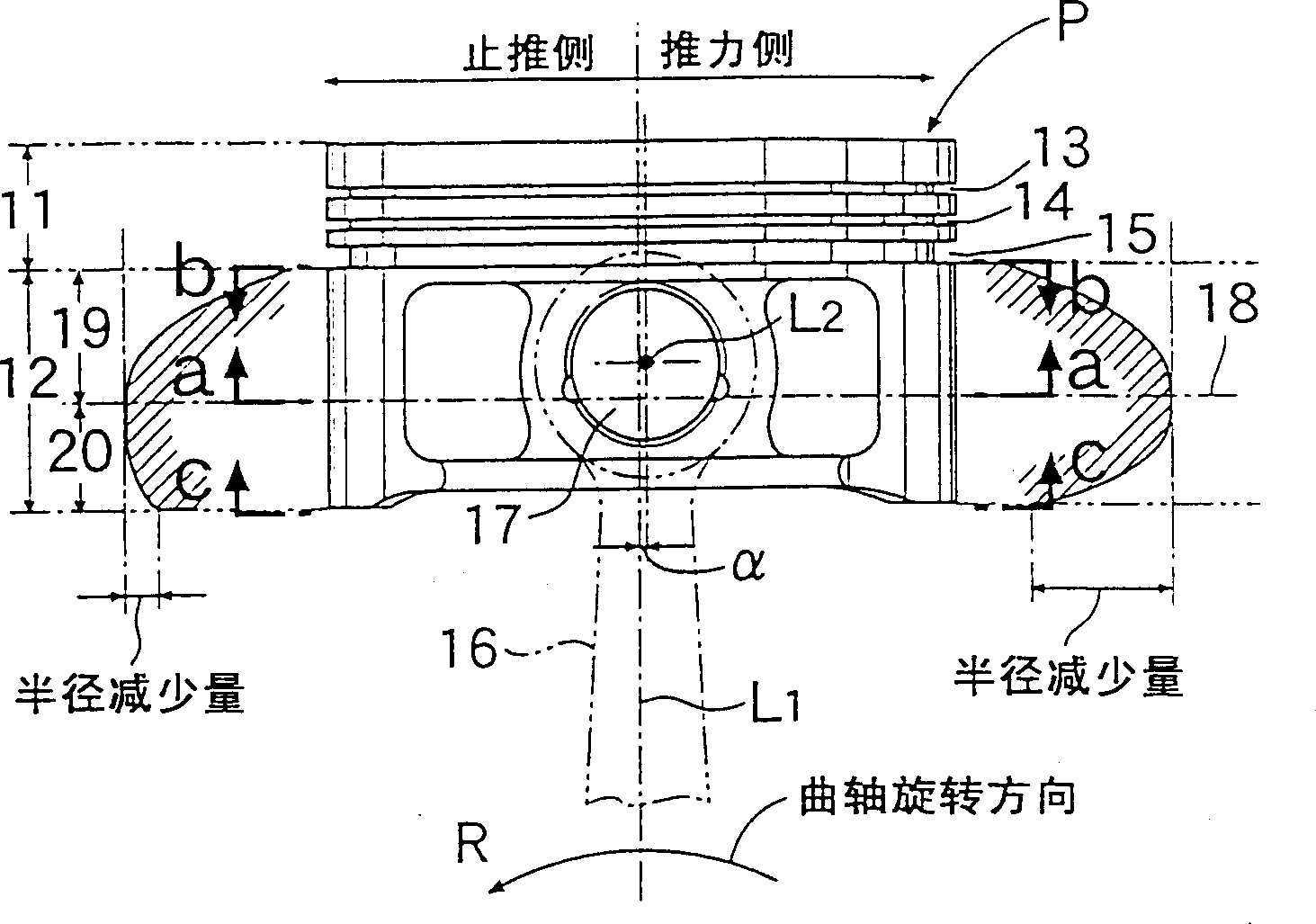
[0029] figure 1 The piston P of the shown 4-stroke cycle internal combustion engine comprises a piston crown 11 facing the combustion chamber and a skirt 12 facing the crankcase. Two compression ring mounting grooves 13 and 14 and an oil ring mounting groove 15 are defined on the piston top 11 . A connecting rod 16 is swingably connected at its small end to the skirt 12 via a piston pin 17 .

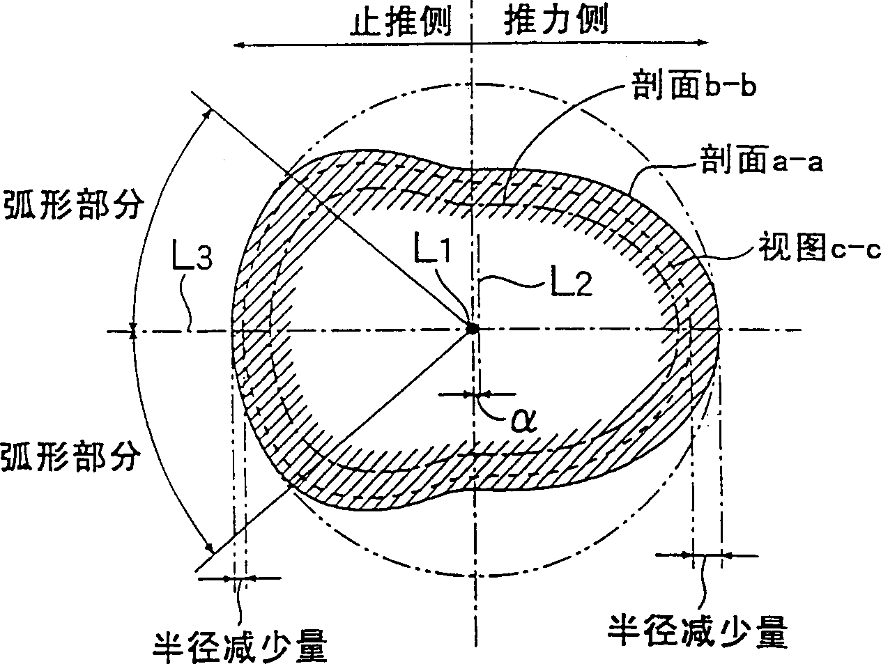
[0030] The cross-sectional shape of the skirt 12 of the piston P is along the cylinder axis L 1 changes continuously in the direction. More specifically, the skirt 12 is at its vertical middle portion (along the cylinder axis L 1 direction) has a maximum diameter portion 18, and the upper skirt 19 and the lower skirt 20 are separated from each other by the maximum diameter portion 18. The largest diameter portion 18 is the portion of the skirt 12 that has the l...


PUM


Abstract

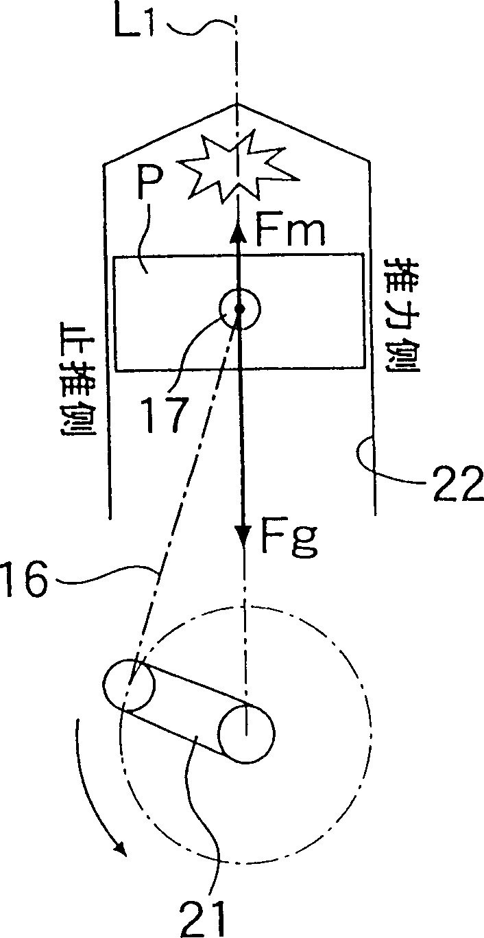
An object of the present invention is to effectively achieve the reduction in piston slap sound in both of an expansion stroke and a compression stroke in consideration of a difference between the behaviors of a piston in the expansion stroke and the compression stroke. For this purpose, in a piston P having a skirt 12 formed into an intermediately bulged barrel type, the axis L2 of a piston pin is offset with respect to the cylinder axis L1, and the decrement in radius of a lower skirt portion 20 is set to be large on a thrust side and small in an anti-thrust side. In the expansion stroke, the piston is positively swung, while the skirt 12 is put into abutment against a wall surface of a cylinder bore, thereby reducing the piston slap sound.

Description

technical field [0001] The present invention relates to internal combustion engine pistons having skirts, and more particularly to piston shapes that reduce piston rattle. Background technique [0002] In an internal combustion engine piston, the piston comprises a piston pin having an axis offset relative to the cylinder axis and a skirt forming a centrally convex barrel shape. From the Japanese Utility Model Publication No. 53-40546 can know such a technology: partially cut away the upper part of the skirt portion on the side opposite to the offset side of the piston pin, and the upper part of the cut away is easy to Causes scratches and spots between the wall surface of the cylinder bore and this part, thus preventing seizing. [0003] The barrel shaped skirt tends to reduce the piston rattle produced by the piston hitting the cylinder bore wall, but in the known pistons described above an improvement is made in the upper barrel shape of the skirt from a lubrication poin...

Claims


Application Information

Patent Timeline
IPC IPC(8): F02F3/00F02F3/02F16J1/02F16J1/04
CPCF16J1/02F02F3/022F16J1/04
Inventor 嶽和秀平出玲子河合范明
Owner HONDA MOTOR CO LTD
Learn More