
High-efficiency engine

An engine and high-efficiency technology, applied in the direction of machine/engine, mechanical equipment, etc., can solve the problems of large lateral force on the piston, serious friction and wear, etc., to reduce knocking, improve thermal power conversion rate, and reduce the amount of formation. Effect

Inactive Publication Date: 2007-09-26
靳宇男
View PDF0 Cites 13 Cited by
  • Summary
  • Abstract
  • Description
  • Claims
  • Application Information

AI Technical Summary

Problems solved by technology

[0003] In order to solve the above-mentioned technical problems that the piston of the traditional engine is subject to a large lateral force, severe friction and wear, and cannot efficiently convert the heat energy of fuel combustion when the piston is near the top dead center, the present invention provides a high-efficiency engine: comprising a cylinder, a piston , guide body, piston pin and connecting rod, a movable connection device is provided between the piston and the guide body, the movable connection device is set as a pre-compressed spring or a non-elastic connection device, and the guide body and the connecting rod are movable connect

Method used


Image

  • High-efficiency engine
  • High-efficiency engine
  • High-efficiency engine

Examples


Embodiment 1

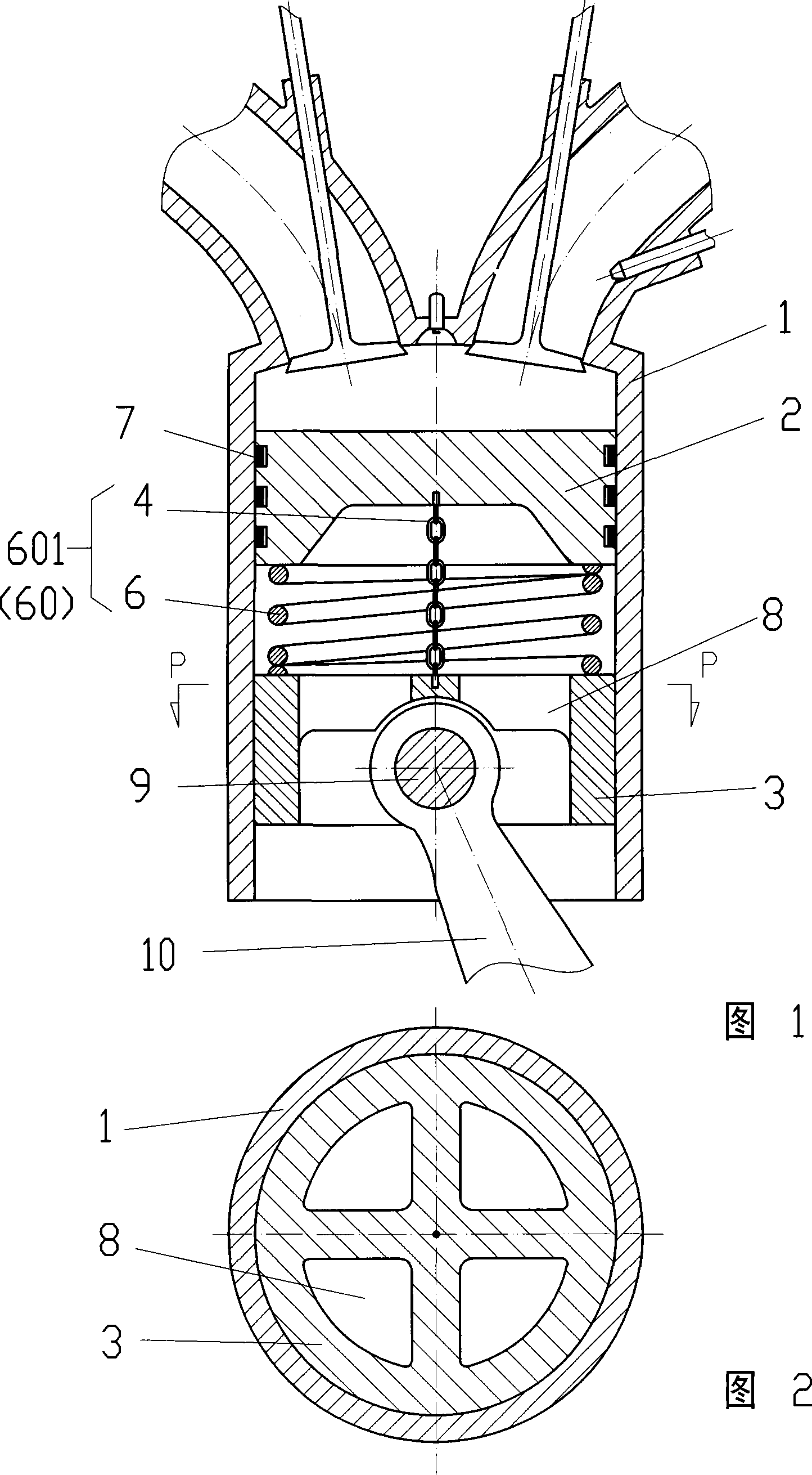
[0022] The high-efficiency engine shown in Figure 1 and Figure 2 includes a cylinder 1, a piston 2, a guide body 3, a piston pin 9 and a connecting rod 10, and a movable connection device 60 is arranged between the piston 2 and the guide body 3, The movable connection device 60 is configured as a pre-compressed spring 601 , and the guide body 3 is movably connected with the connecting rod 10 .

[0023] The guide body 3 is set as a slider structure 3 that is in sliding contact with the lower section of the cylinder 1 and is connected with the connecting rod 10 through the piston pin 9. The slider structure 3 is provided with a fluid channel 8, and the piston 2 In sealing and sliding contact with the upper section of the cylinder 1, the precompression spring 601 is composed of a spring 6 and a stretch limiting cable chain 4, one end of the stretch limiting cable chain 4 is connected to the piston 2, and the other end is connected to the slider structure The body 3 is connected, ...

Embodiment 2

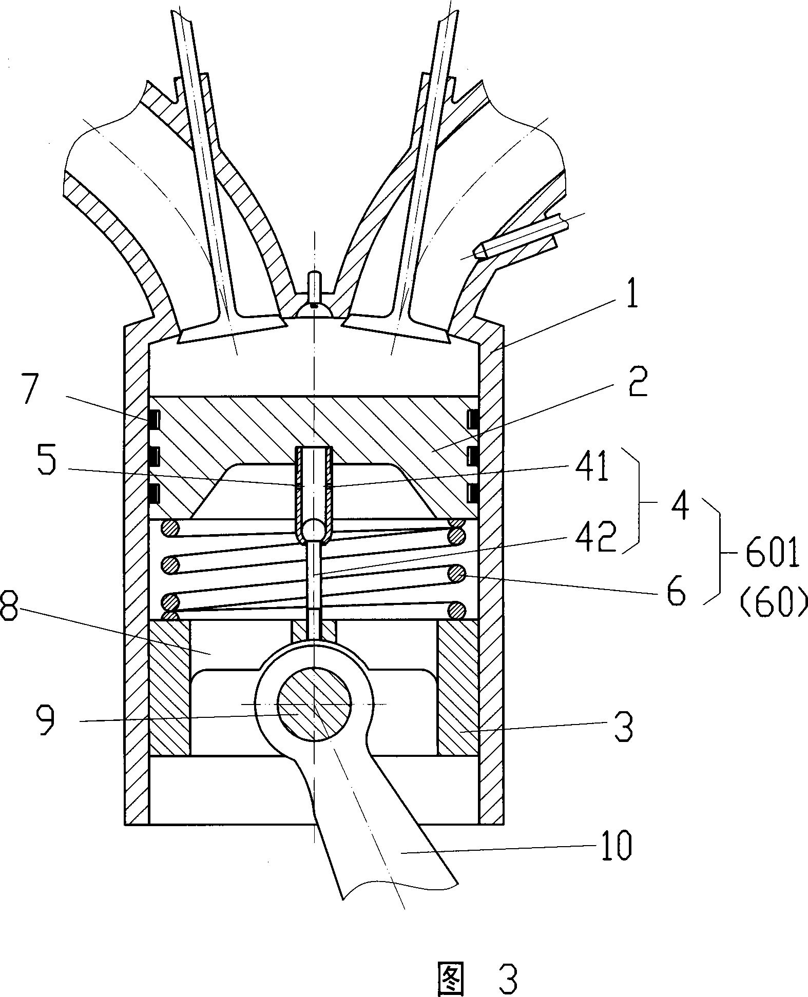
[0025] In the high-efficiency engine shown in Figure 3, the precompression spring 601 is composed of a spring 6 and a stretch limiter 4, one end of the stretch limiter 4 is connected to the piston 2, and the other end is connected to the slider structure 3 connection, the extension-limiting sleeve rod 4 is composed of a ball-end bushing 41 and a ball-end rod 42, the ball-end bushing 41 is provided with an oil hole 5, and the rest of the structure is the same as in Embodiment 1.

Embodiment 3

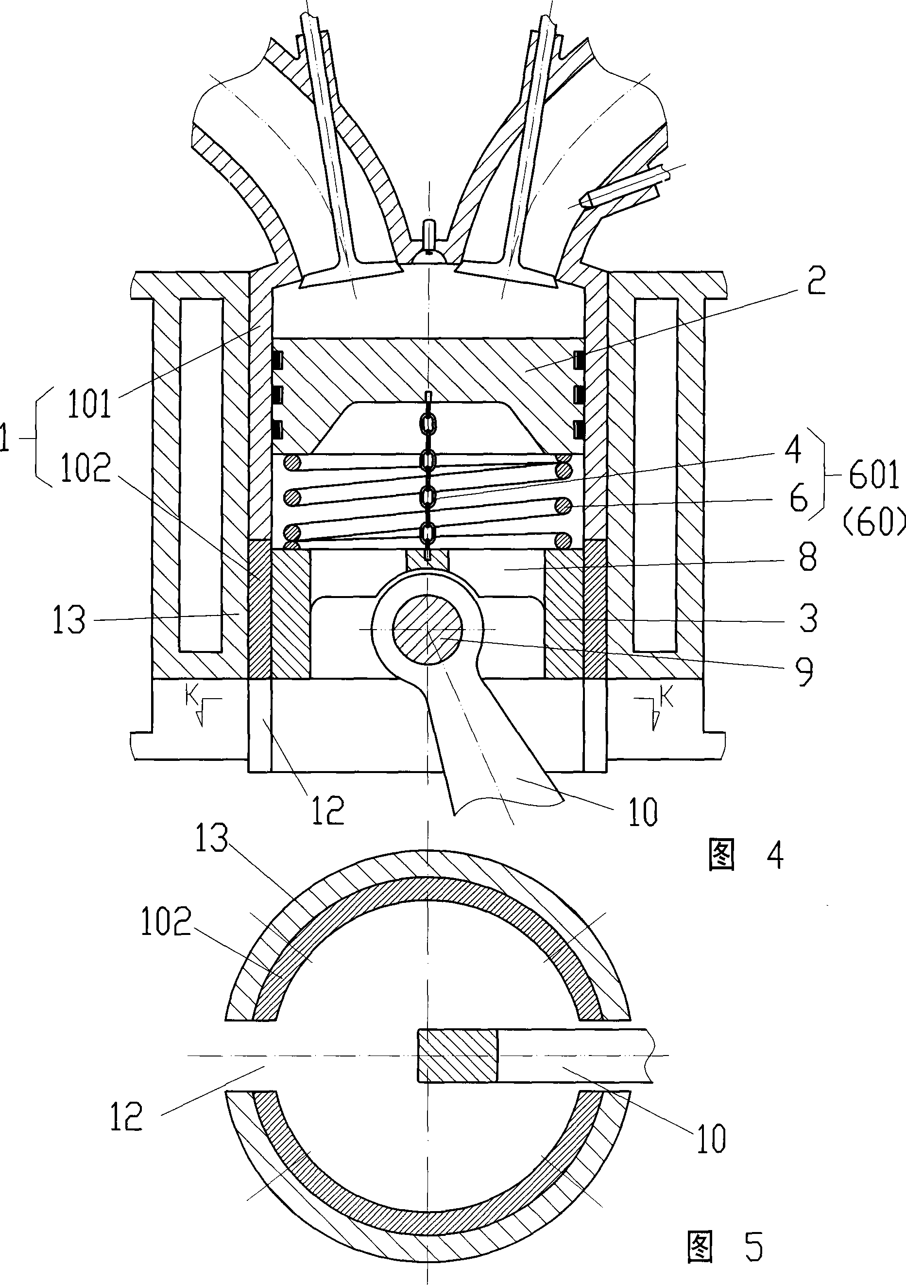
[0027] As for the high-efficiency engine shown in Figures 4 and 5, the cylinder 1 is set as an upper cylinder 101 and a lower slide 102, and the lower slide 102 can be set to be equal or unequal to the upper cylinder 101, or Can be made as non-drum type, also can be provided with opening 12, all the other structures are with embodiment 1.


PUM


Abstract

A highly efficient engine comprises the cylinder, piston, guide, piston pin and linking lever with active linking device between the piston and the guide, with the linking device setting as prepressure shrinkable spring or nonspring linking device with the guide connecting with the linking lever. With better location of the guide having low temperature and better lubrication, and the piston bearing up and down forces, it can greatly reduce the friction and wearing between the piston and the cylinder. Apart from that, it can quickly reduce the top dead end high temperature and pressure retain time, with greatly reduced shock, improved torque, with higher, more efficient, energy saving and environment protective design.

Description

technical field [0001] The invention relates to a high-efficiency engine. Background technique [0002] In a traditional engine, the piston is a whole, and the piston is subject to a large lateral force, which results in large friction and wear. Moreover, at the beginning of the power stroke, that is, within a period of time from the ignition of the spark plug, because the piston is near the top dead center, the piston The torque of the force acting on the crankshaft through the connecting rod is almost zero, so the fuel combustion at this stage does almost no work, and because the gas does not expand much before the crankshaft leaves the top dead center to a certain extent, the high temperature and high pressure can be maintained for a long time , large heat loss, NO X Etc. emissions are high, so it is urgent to invent a piston that is not subject to lateral force, and when a pre-compressed spring is used to connect the piston and the guide body, it can quickly reduce the ...

Claims


Application Information

Patent Timeline
Patent Type & Authority Applications(China)
IPC IPC(8): F02B75/32
Inventor 靳宇男
Owner 靳宇男
Learn More