Control apparatus for internal combustion engine

a control apparatus and internal combustion engine technology, applied in the direction of electric control, ignition automatic control, machines/engines, etc., can solve the problems of easy to reach torque fluctuation limits and adverse knocks, and achieve the effects of reducing knocks, increasing torque fluctuation, and increasing burning velocity

Inactive Publication Date: 2017-08-10
TOYOTA JIDOSHA KK
View PDF4 Cites 13 Cited by
  • Summary
  • Abstract
  • Description
  • Claims
  • Application Information

AI Technical Summary

Benefits of technology

[0007]Where the retard of the spark timing for reducing knock is executed in association with a fuel increment for enriching the air-fuel ratio, it is required to appropriately determine the value of the fuel increment. This is because, if the value of the fuel increment is too large, a knock may be adversely induced due to an increase in the burning velocity, and because if the value of the fuel increment is too small, a torque fluctuation limit may be easy to be reached.
[0008]The present disclosure has been made to address the problem described above, and an object of the present disclosure is to provide a control apparatus for an internal combustion engine that is configured, when retarding the spark timing for reducing knock, to be able to accompany a fuel increment for enriching the air-fuel ratio in such a manner as to be able to appropriately control the value of the fuel increment in terms of reducing knock and an increase of torque fluctuation.
[0012]According to the control apparatus for an internal combustion engine of the present disclosure, if the spark timing is retarded for reducing knock, an increment of injected fuel is executed in such a manner that the actual combustion index value at the retard execution cycle approaches the target combustion index value at the before-retard cycle. Therefore, the difference between the actual combustion index values at the combustion cycles before and after the execution of the retard of the spark timing can be decreased. With the retard of the spark timing in association with the enrichment of the air-fuel ratio by this kind of fuel increment, the spark timing can be retarded while the torque fluctuation limit can be caused to be harder to be reached as compared with an example of executing only the retard of the spark timing. In addition, an injected fuel is incremented in such a manner that a change of the actual combustion index value as a result of execution of the retard of the spark timing is reduced, and an increase of the burning velocity due to an excessive fuel increment can thereby be reduced. Therefore, a knock can be prevented from being adversely induced due to a fuel increment being executed in association with the retard of the spark timing. As described above, according to the control apparatus of the present disclosure, an increment of injected fuel for enriching the air-fuel ratio can be executed in association with the retard of the spark timing in such a manner as to be able to appropriately control the value of the fuel increment in terms of reducing knock and an increase of torque fluctuation.

Problems solved by technology

This is because, if the value of the fuel increment is too large, a knock may be adversely induced due to an increase in the burning velocity, and because if the value of the fuel increment is too small, a torque fluctuation limit may be easy to be reached.

Method used


Image

  • Control apparatus for internal combustion engine
  • Control apparatus for internal combustion engine
  • Control apparatus for internal combustion engine

Examples


first embodiment

[Control in First Embodiment]

[0027](Calculation of Measured Data of MFB Utilizing in-Cylinder Pressure Sensor)

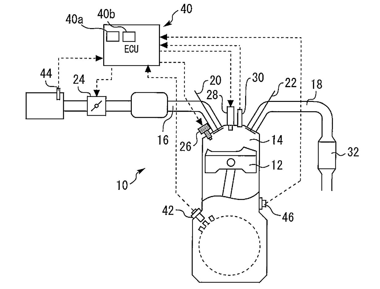
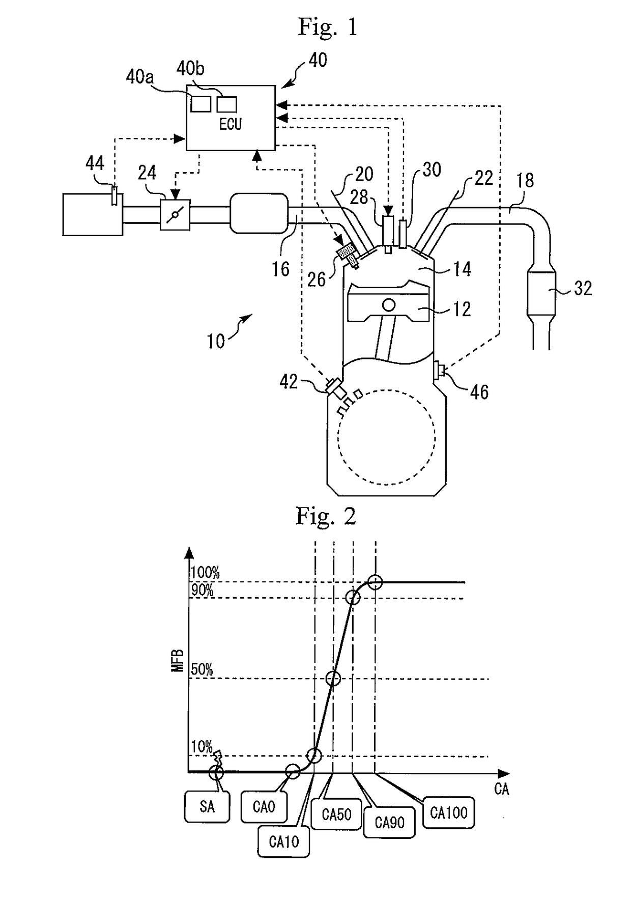
[0028]FIG. 2 is a view that represents a waveform of mass fraction burned (MFB) and a spark timing (SA). According to the system of the present embodiment that includes the in-cylinder pressure sensor 30 and the crank angle sensor 42, in each cycle of the internal combustion engine 10, measured data of an in-cylinder pressure P can be acquired in synchrony with a crank angle (more specifically, a set of in-cylinder pressures P that are calculated as values for the respective predetermined crank angles). A heat release amount Q inside a cylinder at an arbitrary crank angle θ can be calculated according to the following equations (1) and (2) using the measured data of the in-cylinder pressure P and the first law of thermodynamics. Furthermore, a mass fraction burned (hereunder, referred to as “MFB”) at an arbitrary crank angle θ can be calculated in accordance with the followi...


PUM


Abstract

A control apparatus for an internal combustion engine is provided to calculate, on the basis of the output values of the in-cylinder pressure sensor, a combustion index value which indicates the stability of combustion. If reduction of knock is required, the spark timing is retarded. An increment of injected fuel is executed in such a manner that a combustion index value that indicates the actual stability of combustion at a retard execution cycle that is a combustion cycle at which the retard of the spark timing is executed approaches a target value of a combustion index value that indicates the stability of combustion at a before-retard cycle.

Description

CROSS-REFERENCE TO RELATED APPLICATION[0001]This application is based on and claims the benefit of Japanese Patent Application No. 2016-021968, filed on Feb. 8, 2016, which is incorporated by reference herein in its entirety.BACKGROUND[0002]Technical Field[0003]The present disclosure relates to a control apparatus for an internal combustion engine.[0004]Background Art[0005]For example, JP 4-187851A discloses a spark ignition internal combustion engine that includes a fuel injection valve for directly injecting fuel into a cylinder. In this internal combustion engine, if knock occurs, the spark timing is retarded and the amount of fuel injected at the compression stroke is increased.[0006]In addition to JP 4-187851A, JP 2011-174409A is a patent document which may be related to the present disclosure.SUMMARY[0007]Where the retard of the spark timing for reducing knock is executed in association with a fuel increment for enriching the air-fuel ratio, it is required to appropriately det...

Claims


Application Information

Patent Timeline
Patent Type & Authority Applications(United States)
IPC IPC(8): F02D43/04F02D41/30F02P5/152F02D35/02
CPCF02D43/04F02D35/023F02P5/152F02D41/30F02D35/027F02D41/1475F02D2200/101F02D41/1498F02P5/045F02P5/153F02D35/028F02D37/02Y02T10/40
Inventor SUZUKI, YUSUKEFURUISHI, AKIO
Owner TOYOTA JIDOSHA KK
Why Eureka
Try Eureka