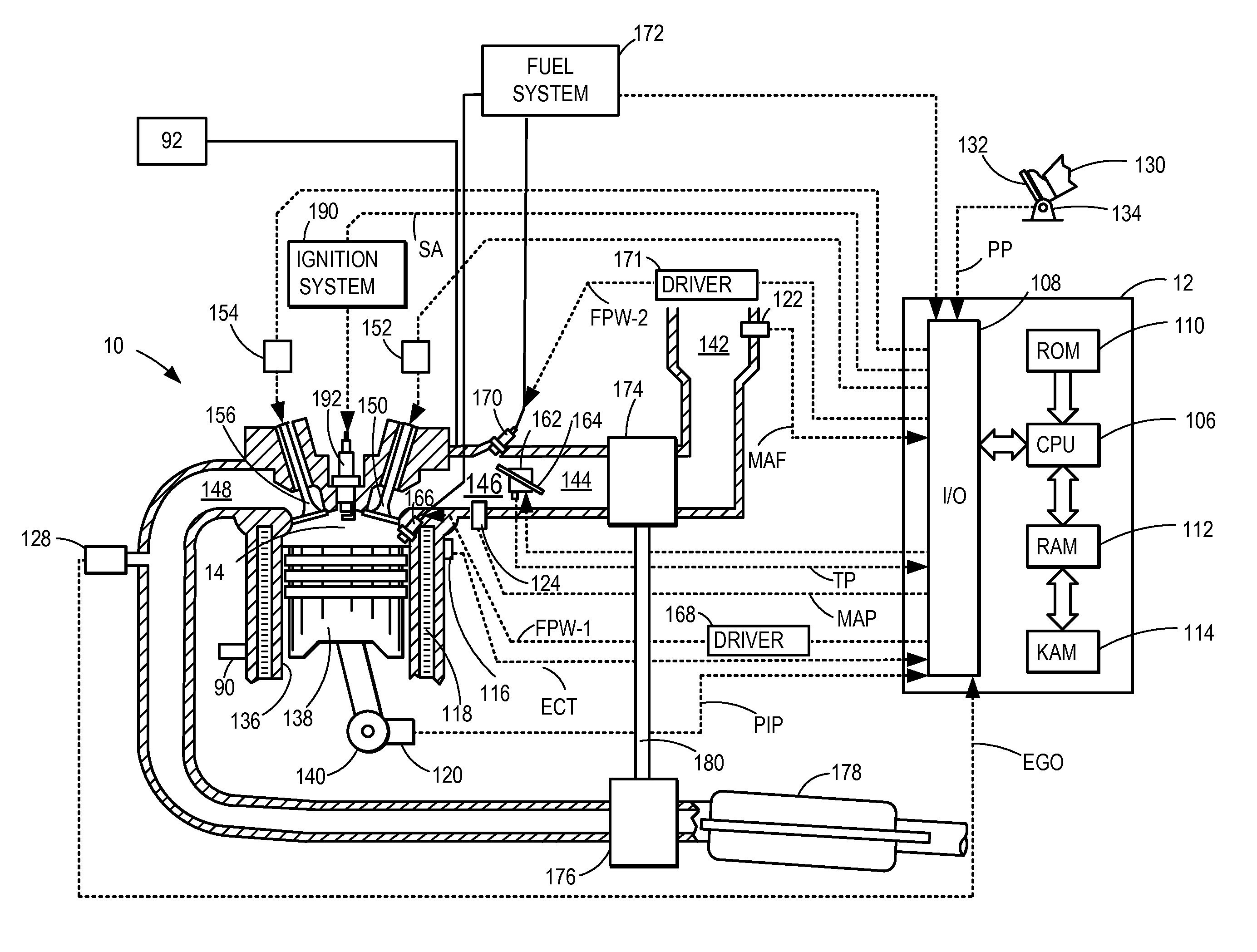
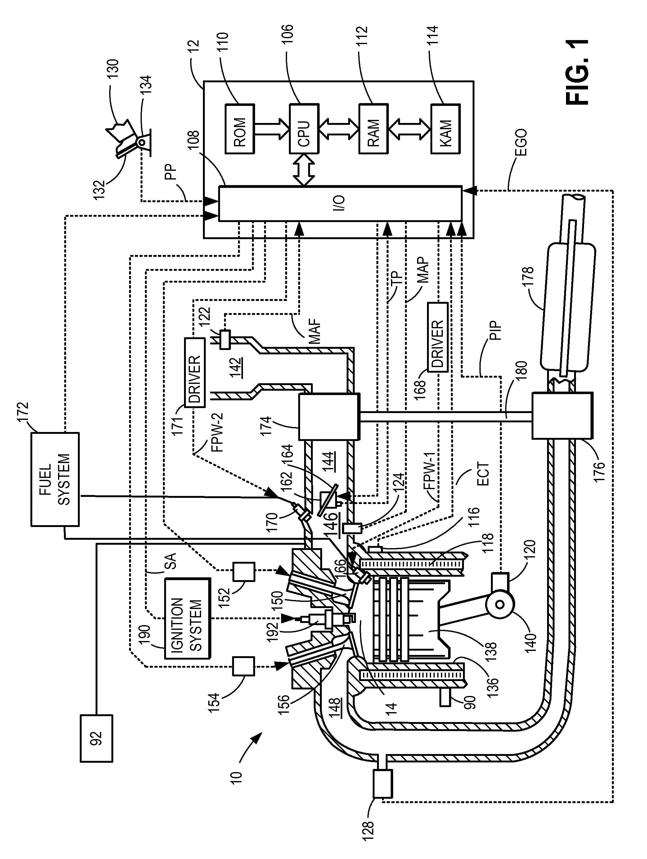
[0002]Engines may be configured with direct fuel injectors that inject fuel directly into a combustion chamber (direct injection), and / or with port fuel injectors that inject fuel into an intake port (port fuel injection). The combined use of port injection and direct injection of a fuel allows the various benefits of each type of injection to be leveraged. For example, with port fuel injectors, the fuel is typically sprayed into the intake valves and ports. The injected fuel evaporates primarily due to contact with hot metal surfaces and / or due to backflow of hot exhaust gases during valve overlap. In contrast, with direct fuel injectors, fuel is sprayed directly into the combustion chamber and the injected fuel evaporates primarily due to smaller droplet size and thorough mixing. In addition, since there is little impingement of fuel onto metal surfaces, direct fuel injection results in more evaporative cooling of the aircharge.
[0003]Engine control systems may vary a ratio of fuel injected via port injection and direct injection based on operating conditions. In one approach, as shown by Glugla in U.S. Pat. No. 8,037,874, a larger proportion of fuel is provided to a cylinder via direct injection in response to an indication of knock. Therein, at high loads, when the engine is knock-limited, the increased evaporative cooling of the direct injection and denser aircharge at wide open throttle conditions results in improved volumetric efficiency, leading to higher torque and power at the high load conditions. In addition, the cylinder charge cooling mitigates knock. In contrast, at part-load conditions, direct injection results in a small but measurable penalty in pumping work. This is because the increased evaporative cooling from direct fuel injection results in a denser aircharge which requires the engine to be throttled more to provide a desired torque output. To reduce this penalty, engine control systems may use a higher proportion of port injection at low-load and mid-load conditions.
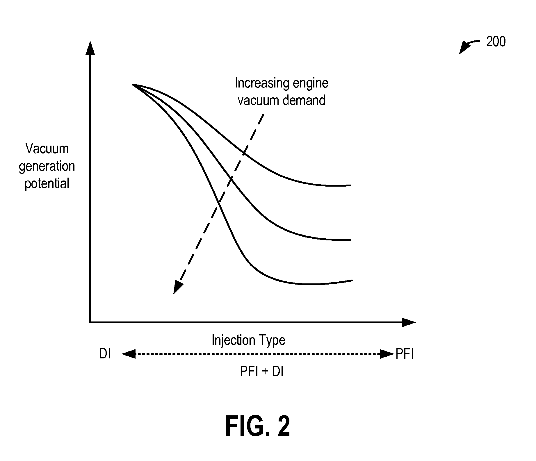
[0005]In one example, the above advantages can be achieved by a method of operating an engine comprising, in response to engine vacuum generation being lower than an engine vacuum demand, increasing a proportion of fuel injected into a cylinder via direct injection while correspondingly decreasing a proportion of the fuel injected into the cylinder via port injection. In this way, the increased throttling and pumping work associated with direct injection of a fuel at low-to-mid engine loads can be advantageously used to generate more vacuum at the engine.
[0006]In one example, an engine may be configured with both direct injection and port fuel injection of a fuel to the engine cylinders. An initial fuel injection amount, including a proportion of fuel to be injected into the cylinder via the direct injector relative to the port fuel injector, may be determined based on engine operating conditions, such as engine speed-load conditions. For example, during part-loads (e.g., low-to-mid engine loads), the initial fuel injection amount may include a higher proportion of port injection and a lower proportion of direct injection to improve engine pumping efficiency. In response to an increased vacuum demand during these conditions, such as for purging a fuel vapor canister, for crankcase ventilation, or for actuating a brake booster, the initial fuel injection amount may be adjusted. Specifically, the fuel injection amount may be shifted to include a higher proportion of direct injection and a correspondingly lower proportion of port injection of the given fuel. By increasing direct injection, a pumping work required to meet the torque demand is increased, leading to adjustment of an air intake throttle. The increased throttling lowers intake manifold pressure and increases vacuum generation. The increased vacuum allows the engine vacuum demand to be better met.
[0007]In this way, fuel injection to an engine cylinder may be adjusted based on an engine vacuum demand. Specifically, a shift from increased port injection of a fuel to increased direct injection of the fuel can be used to take advantage of the increased pumping work, and decreased manifold pressure level, associated with the direct injection. This allows the interaction of the inefficiencies of a direct injection system with engine vacuum generation to be leveraged to meet engine torque demand and vacuum demand. Overall, the pumping efficiency provided by port fuel injection is traded for the vacuum generation efficiency provided by direct fuel injection.

