Tubular lamp and mfg. method thereof

A manufacturing method and technology for tubular lamps, which can be applied to incandescent lamps, discharge lamps, discharge tubes, etc., can solve the problems of increased cost, manual operation, and reduced production efficiency.

Inactive Publication Date: 2004-06-30
PANASONIC CORP
View PDF0 Cites 0 Cited by
  • Summary
  • Abstract
  • Description
  • Claims
  • Application Information

AI Technical Summary

Problems solved by technology

Therefore, the problem that the above-mentioned method exists is: must re

Method used


Image

  • Tubular lamp and mfg. method thereof
  • Tubular lamp and mfg. method thereof
  • Tubular lamp and mfg. method thereof

Examples


Embodiment Construction

[0027] Embodiments of the present invention will be described below with reference to the drawings.

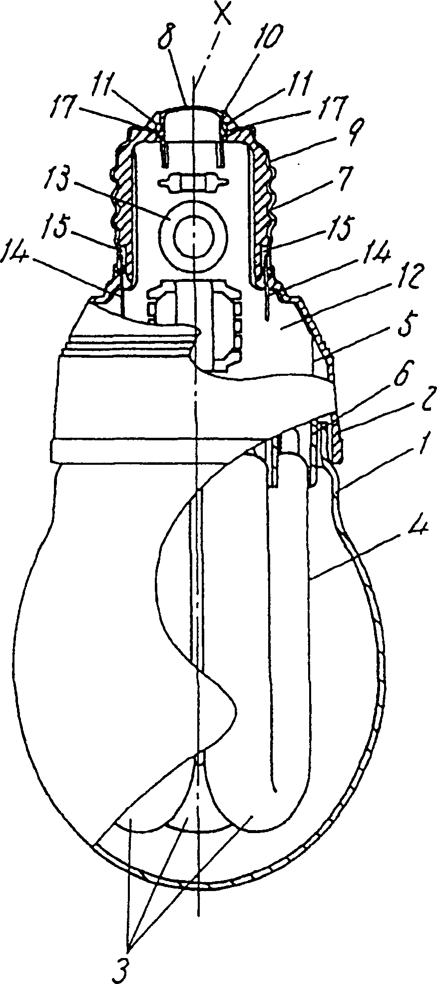
[0028] The bulb-type fluorescent lamp of the first embodiment of the present invention with a rated power of 13W has an overall length of 120 mm and a maximum outer diameter of 60 mm. Such as figure 1 As shown, in a peripheral device formed by a light-transmitting glass shell 1 and a resin tube shell 2, a fluorescent tube 4, which is bridged by three U-shaped tubes 3 with an outer diameter of 11mm to form a discharge circuit, is installed. A lighting circuit 5 for lighting the tube 4 , and a holder 6 that holds one end of the fluorescent lamp 4 and holds the lighting circuit 5 on the opposite side of the fluorescent tube 4 .

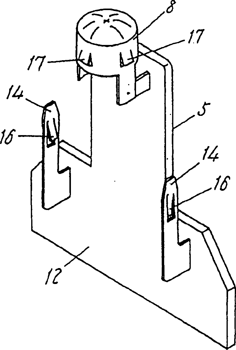
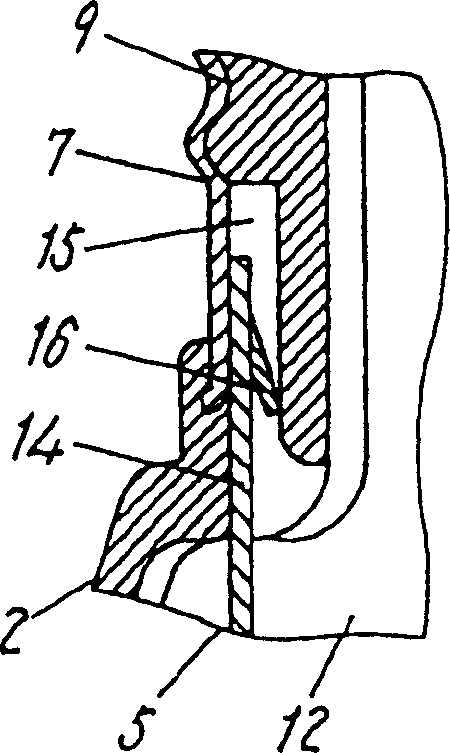
[0029] At one end of the case 2, a socket portion 7 to be inserted into a base (not shown) of a lighting fixture is formed. The socket part 7 has an eyelet 8 and a base 9 which are in electrical contact with the base. Furthermore, an eye socket porti...


PUM


Abstract

The present invention provides a tube lamp and its manufacturing method which allow a lighting circuit and a shell to be easily and reliably connected together, which enable automation of a step of connecting the lighting circuit and the shell together, and which require low costs while achieving a high production efficiency. The tube lamp includes a case (2) having a shell (9) at an end thereof, and a lighting circuit (5) housed in the case (2) and having a printed circuit board (12) with a circuit part (13) mounted thereon, wherein the shell (9) and the lighting circuit (5) are connected together without leads.

Description

technical field [0001] The present invention relates to tubular lamps and methods for their manufacture. Background technique [0002] Conventional tubular lamps such as light bulb fluorescent lamps such as Figure 16 Shown, be that the lighting circuit 38 that fluorescent tube 4 and this fluorescent tube lighting usefulness are housed in the peripheral device that is made of glass bulb 1 and tube shell 37. [0003] A socket 41 having an end eye 39 and a lamp cap 40 is screwed to one end of the tube shell 37 . [0004] The lighting circuit 38 has two lead wires 42 and 43 for power supply. A wire 42 is drawn out from a through hole 44 provided on the terminal eye 39, and is soldered and connected to the outside of the terminal eye 39 with solder as an electrical connection. [0005] Another wire 43 is drawn out of the tube shell 37, and is electrically connected to the outside of the lamp holder 40 by soldering. [0006] However, this conventional tubular lamp is connected...

Claims


Application Information

Patent Timeline
IPC IPC(8): H01J5/54H01J61/32H01J61/56
CPCH01J5/54H01J61/56H01J61/327H01J61/34
Inventor 松叶彻夫觉野吉典
Owner PANASONIC CORP
Why Eureka
Try Eureka