Magnetically suspended rotator with single electromagnetic winding

A technology of electromagnetic coils and rotating devices, which is applied in the direction of holding devices and electrical components using magnetic attraction or thrust, and can solve the problems of increasing motors and complicating structures.

Inactive Publication Date: 2004-06-30
UNIV OF SCI & TECH OF CHINA
View PDF2 Cites 9 Cited by
  • Summary
  • Abstract
  • Description
  • Claims
  • Application Information

AI Technical Summary

Problems solved by technology

In practical applications, the mechanical driving force is also used to replace the function of the electromagnetic auxiliary coil, but at this time, the motor needs to be...

Method used


Image

  • Magnetically suspended rotator with single electromagnetic winding
  • Magnetically suspended rotator with single electromagnetic winding
  • Magnetically suspended rotator with single electromagnetic winding

Examples


Embodiment Construction

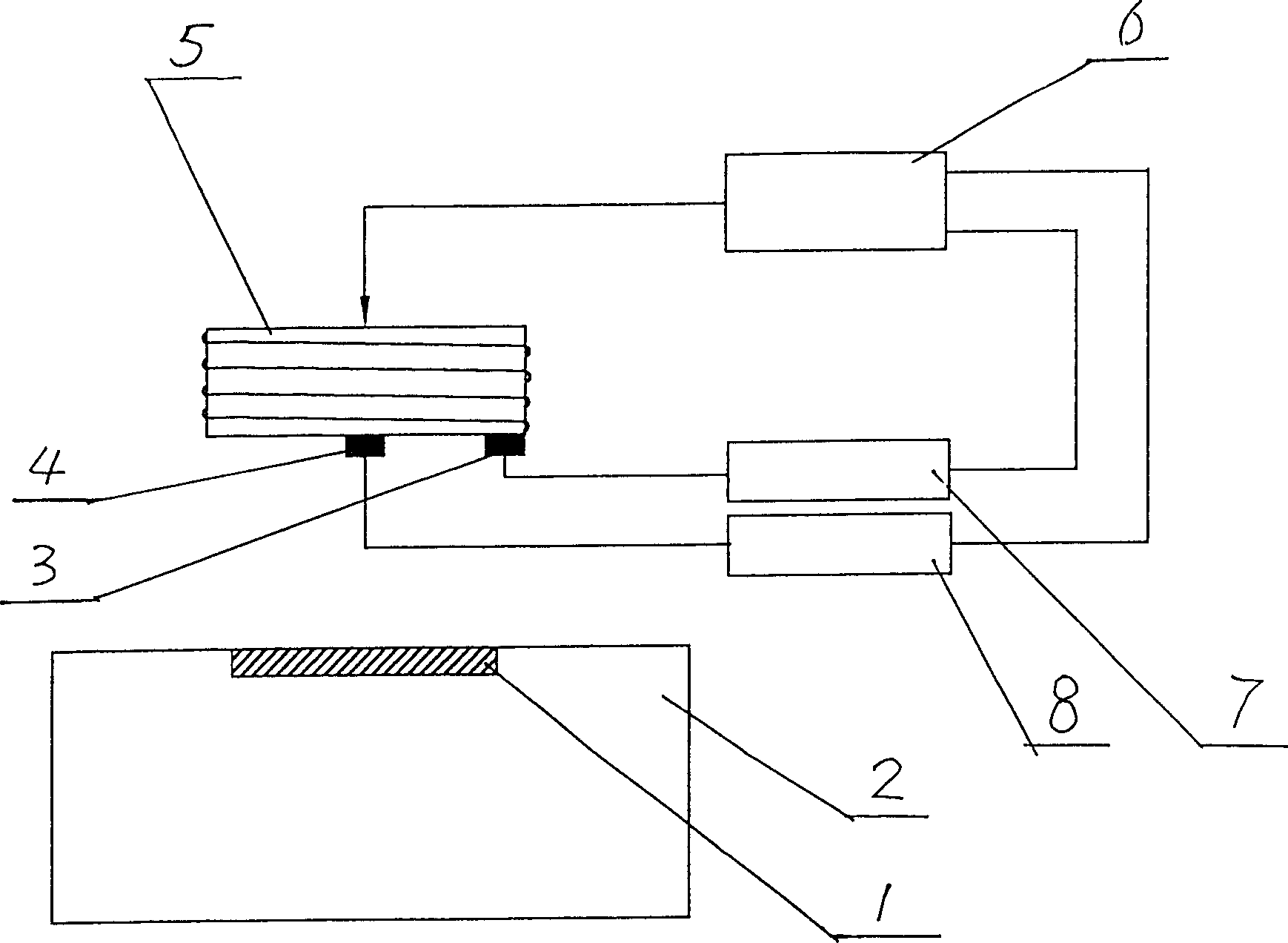
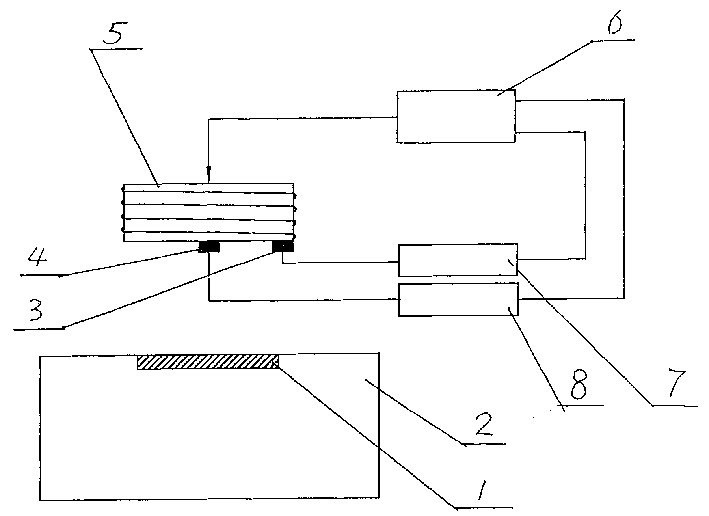
[0011] see figure 1 , which is a rectangular permanent magnet 1 placed on a suspended object 2 . Near the top of the suspended object, there is a rectangular electromagnetic coil 5, which is opposite to the rectangular permanent magnet 2, but the electromagnetic coil and the rectangular permanent magnet are dislocated by 90 in its initial state. , that is: the length direction of the electromagnetic coil is parallel to the width direction of the rectangular permanent magnet. A vertical position Hall sensor 4 is provided at the center of the lower part of the electromagnetic coil 5, and a circumferential position Hall sensor 3 is provided at the periphery of the lower part of the electromagnetic coil 5. 6 is an excitation current control circuit. 7 is the signal processing circuit of the position in the circumferential direction. 8 is the signal processing circuit of the position in the vertical direction.

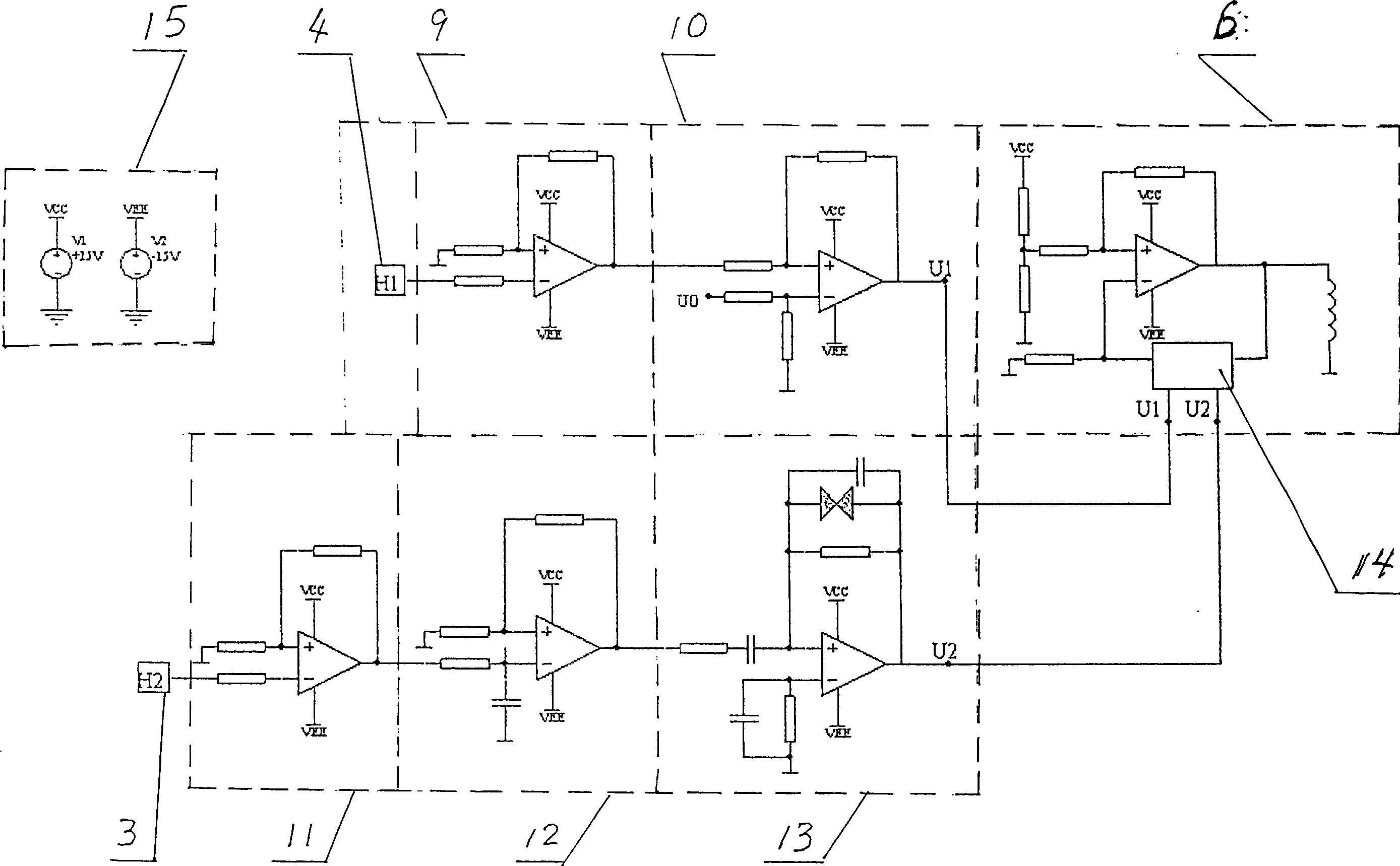
[0012] see figure 2 , 4 is the vertical direction position Hall s...


PUM


Abstract

A magnetically suspended rotator with single electromagnetic coil is composed of suspended body and electromagnetic coil for generating magnetic field. The iron core of said electromagnetic coil has rectangular cross-section. On the suspended body, there are rectangular permanent magnets. On the surface of said electromagnetic coil, there are two sensors for detecting vertical direction and circumferential direction and connected with the control circuit of electromagnetic coil. Said control circuit consists of position sensor, signal processing circuit, and controlling circuit of exciting current. Its advantages are simple structure and high symmetry.

Description

technical field [0001] The invention relates to the magnetic levitation application technology. Background technique [0002] In the prior art, the general magnetic levitation rotating device needs to use two electromagnetic coils, one of the main coils generates an electromagnetic field to levitate the object, that is, provides the levitation force, and then uses another biased electromagnetic auxiliary coil to generate a periodically changing magnetic field effect On a suspended object, it provides a turning force, so that the suspended object can rotate continuously. Since the auxiliary electromagnetic coil needs to be biased, this structure is not suitable for occasions that require symmetry of the overall structure. In practical applications, the mechanical driving force is also used to replace the function of the electromagnetic secondary coil, but at this time, a motor needs to be added, which results in a complicated structure. For example, US5003235A discloses a s...

Claims


Application Information

Patent Timeline
IPC IPC(8): H02N15/00
Inventor 冯志华孔凡让耿鹏翮王建平刘志刚张平刘维来
Owner UNIV OF SCI & TECH OF CHINA
Why Eureka
Try Eureka