Limited run branch prediction

A technology of transfer instructions and operation methods, applied in the direction of program control design, instruments, calculations, etc., can solve problems such as poor efficiency, and achieve the effect of high performance gain

Inactive Publication Date: 2004-07-28
HYUNDAI ELECTRONICS AMERICA +1
View PDF1 Cites 0 Cited by
  • Summary
  • Abstract
  • Description
  • Claims
  • Application Information

AI Technical Summary

Problems solved by technology

So less efficient for shorter runs

Method used


Image

  • Limited run branch prediction
  • Limited run branch prediction
  • Limited run branch prediction

Examples


Embodiment Construction

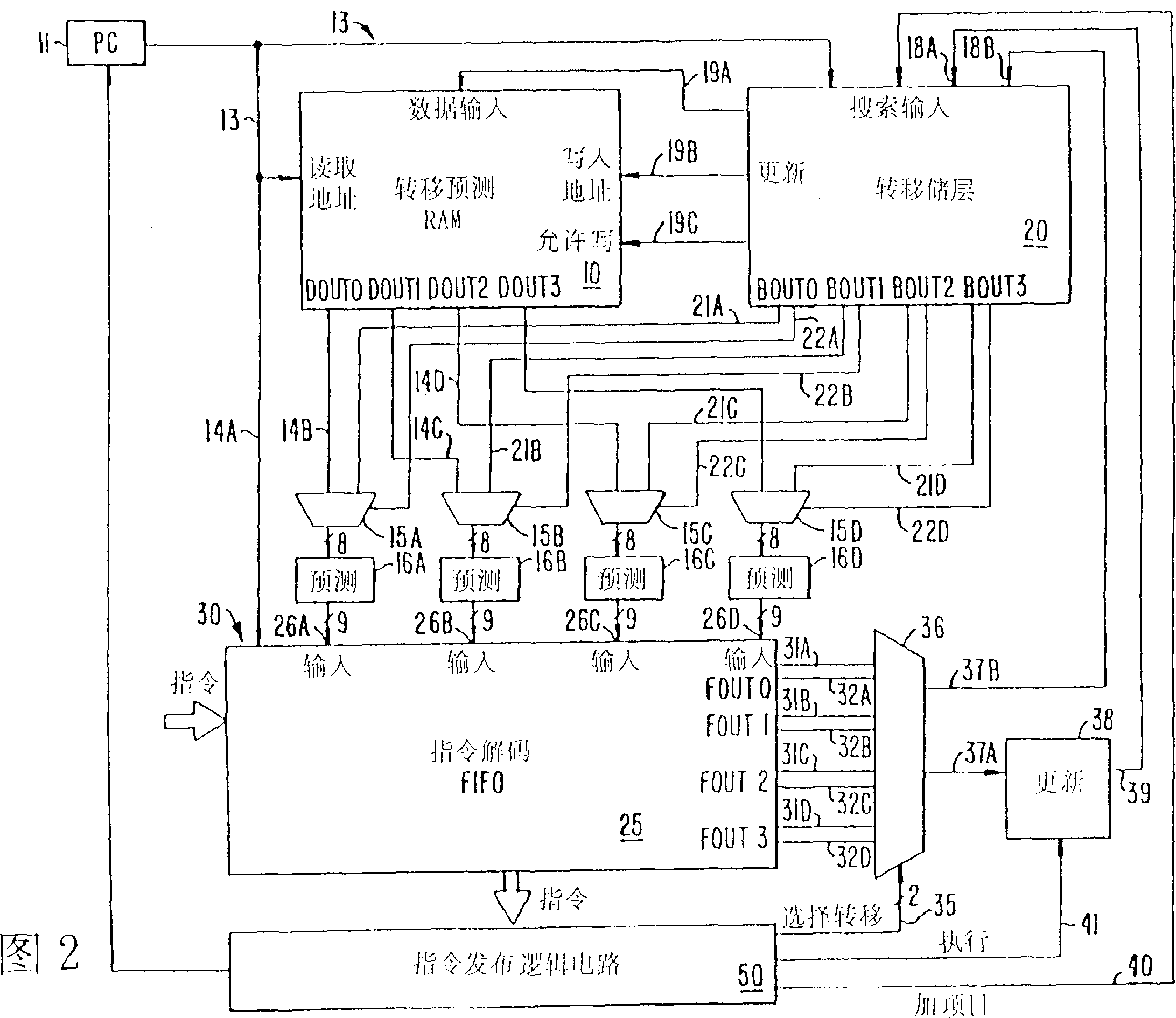
[0027] The preferred embodiment of the invention is associated with a superscalar processor. A superscalar processor fetches and issues multiple -- in this case as many as four -- instructions to the pipeline every clock cycle. Since not all processor elements are relevant to the present invention, some of these elements are not included in the description of the present invention. This is described in US Patent Application Serial No. 07 / 622,893, filed December 5, 1990, entitled "Processor Architecture" by Popescu et al.

[0028] Regarding the prediction of branch instructions and the present invention, the execution history of all branches is stored in two structures, a branch prediction RAM 10 and a branch shelf 20 in the processor. Branch prediction RAM 10 stores the history of all branch executions up to the oldest pending predicted branch, but not including the oldest pending predicted branch itself. Branch store 20 maintains a history of all branch executions that are a ...


PUM


Abstract

A branch prediction technique which increases the likelihood of correctly predicting the direction of a conditional branch instruction is presented. The technique is based on the observation that many branches have run lengths that are constant or slowly-varying. I.e., several consecutive runs of 1's are of the same length. The technique uses the history stored for each branch, which history is enhanced by two small counters, an up counter and a down counter. These counters operate in conjunction with a state machine branch predictor of the prior art for very accurate predictions.

Description

field of invention [0001] The present invention generally relates to a pipeline computer system, and in particular to a branch prediction method adopted by a computer system for predicting the direction of a conditional branch instruction. Background technique [0002] The time required to execute a conditional branch severely limits the performance of a pipelined processor. Processors typically fetch and execute instructions in a sequential fashion; that is, the address of instruction Ei+1 (Ei's successor) to be executed immediately after instruction Ei fetched from address n is found by adding n to the length of Ei . An unconditional branch is an instruction whose execution causes control to be transferred to an instruction at a non-sequential address. Thus a successor of a branch B is fetched from an arbitrary target address. In some computers the target address of branch instruction B is contained in the instruction, while in other computers the target address is form...

Claims


Application Information

Patent Timeline
IPC IPC(8): G06F9/38
CPCG06F9/3844
Inventor 戴维·L·伊萨曼
Owner HYUNDAI ELECTRONICS AMERICA
Why Eureka
Try Eureka