
Ultrasonic beautifying device

An ultrasonic and beauty device technology, applied in the field of ultrasonic beauty devices, can solve problems such as user discomfort, inability to obtain sufficient effects, and temperature rise.

Inactive Publication Date: 2004-09-15
MATSUSHITA ELECTRIC WORKS LTD
View PDF1 Cites 0 Cited by
  • Summary
  • Abstract
  • Description
  • Claims
  • Application Information

AI Technical Summary

Problems solved by technology

[0003] However, in the above-mentioned conventional example, as long as the skin-contacting surface of the probe is in contact with the skin, the ultrasonic vibration will be transmitted, but if the probe is in wrong contact with the skin, the ultrasonic vibration will not be transmitted. without sufficient effect
In addition, since the ultrasonic wave of the output value set by the user is irradiated regardless of whether the probe is in contact with the skin or not, the vibration transmission part (mainly made of metal) of the probe generates heat due to vibration during non-contact. , the temperature of this part rises, and it gives the original user an uncomfortable feeling, which is the problem
Also, even if the ultrasonic vibrating element for generating ultrasonic waves vibrates abnormally, the user still has to wait until the skin is abutted by the probe and receives the ultrasonic waves, which is also a problem.

Method used


Image

  • Ultrasonic beautifying device
  • Ultrasonic beautifying device
  • Ultrasonic beautifying device

Examples


Embodiment Construction

[0026] Embodiment 1

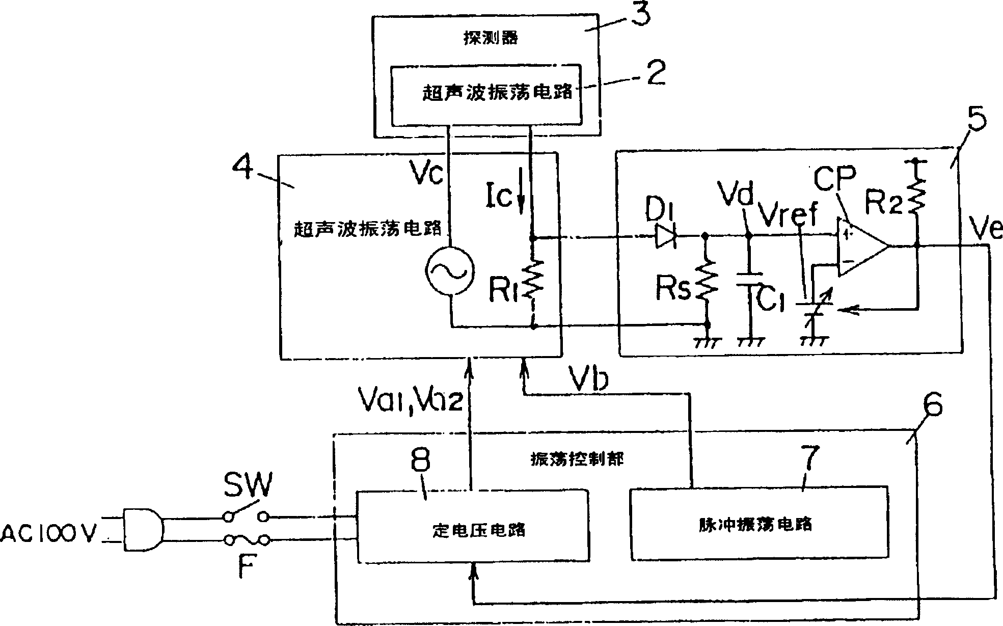
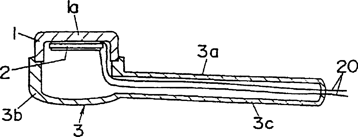
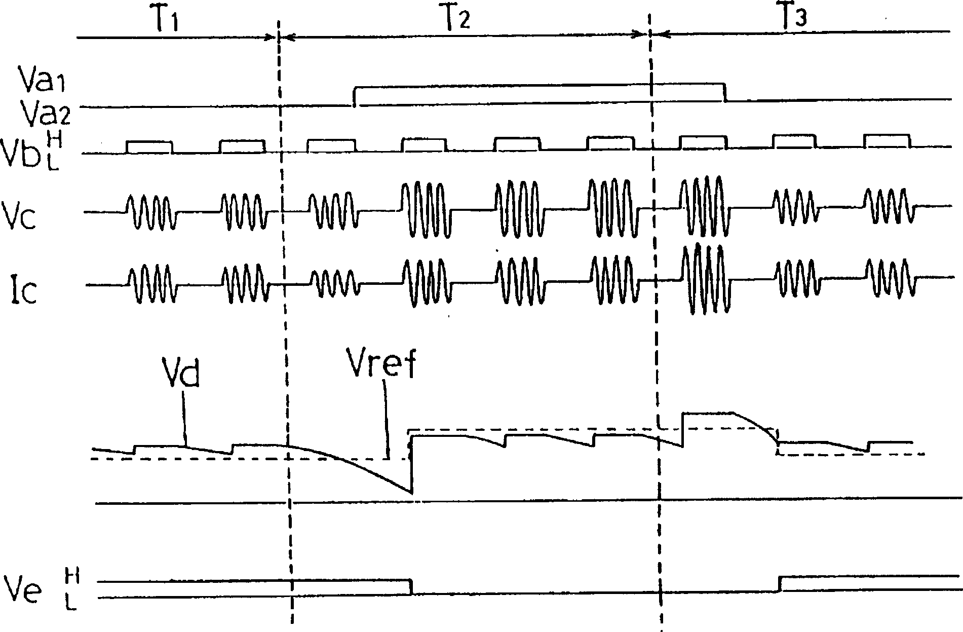
[0027] figure 1 A block diagram of Embodiment 1 of the present invention is shown. The ultrasonic beauty device of this embodiment is equipped with: a probe 3, which is composed of a metal part 1 in contact with the skin and an ultrasonic oscillation element 2 arranged on the opposite side of the skin contact surface 1a of the metal part 1 and installed in a casing 3a; The ultrasonic oscillation circuit 4 drives the ultrasonic vibration element 2 through oscillation output; the sensing circuit 5 is used to sense whether the metal part 1 of the probe 3 is in contact with the skin or not; and the oscillation control part 6 is used to implement the following Control, that is, at least when the sensing circuit 5 senses that the metal part 1 changes from the contact state to the non-contact state to the skin, the output level of the ultrasonic vibration circuit 4 toward the ultrasonic vibration element 2 is compared to the contact state. Low, and when the me...


PUM


Abstract

An ultrasonic beautifying device suppressing unnecessary temperature elevation at a part where a probe is brought into contact with the skin. Since the electrical impedance of an ultrasonic vibrator may vary according to the contact or non-contact of an application member with the skin, a detection circuit detects the contact or non-contact of the application member with the skin by converting the current the ultrasonic vibrator current into a voltage, and a comparator compares this voltage with a reference voltage. When contact is detected by the detection circuit, a constant-voltage circuit sets the level of the constant voltage output to the ultrasonic oscillation circuit at a standard voltage, but when non-contact is detected, the constant voltage is switched to a lower-level constant voltage.

Description

technical field [0001] The invention relates to an ultrasonic beauty device. Background technique [0002] An example of a conventional ultrasonic beauty device is disclosed in Japanese Model No. 3013614. In this conventional example, after applying specific cosmetics on the face, etc. in advance, a probe for ultrasonic irradiation is brought into contact with the applied part to irradiate ultrasonic waves, in order to promote the penetration of cosmetics into the skin effects. Here, ultrasonic waves are always output from the probe regardless of whether the skin-contacting surface of the probe is actually in contact with the skin. [0003] However, in the above-mentioned conventional example, as long as the skin-contacting surface of the probe is in contact with the skin, the ultrasonic vibration will be transmitted, but if the probe is in wrong contact with the skin, the ultrasonic vibration will not be transmitted. and cannot obtain sufficient effect. In addition, sin...

Claims


Application Information

Patent Timeline
IPC IPC(8): A61H23/02
CPCA61H23/0245A61N7/00
Inventor 西村真司林正之
Owner MATSUSHITA ELECTRIC WORKS LTD
Learn More