Signal reception front-end circuit, signal reception circuit, and communication apparatus comprising the same

A signal receiving and front-end circuit technology, applied in the direction of electrical components, demodulation, transmission systems, etc., can solve the problems of IF output level reduction, output level reduction, large error of signal receiving level, etc., and achieve low current consumption Effect

Inactive Publication Date: 2006-02-22
PANASONIC CORP
View PDF0 Cites 2 Cited by
  • Summary
  • Abstract
  • Description
  • Claims
  • Application Information

AI Technical Summary

Problems solved by technology

As a result, the circuit no longer operates and the IF output level is significantly reduced
Also, a significant reduction in the IF output level, resulting in a large error in the signal reception level detected using this IF output level

Method used


Image

  • Signal reception front-end circuit, signal reception circuit, and communication apparatus comprising the same
  • Signal reception front-end circuit, signal reception circuit, and communication apparatus comprising the same
  • Signal reception front-end circuit, signal reception circuit, and communication apparatus comprising the same

Examples


no. 1 example

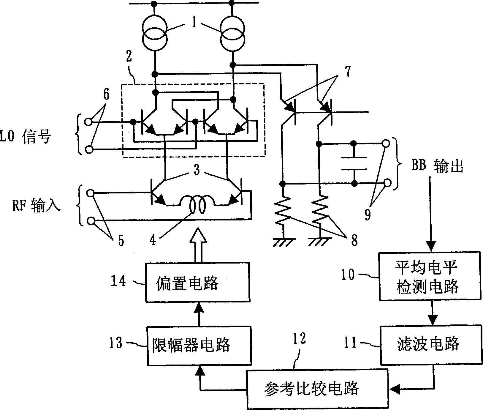
[0031] figure 1 is a block diagram of the structure of the signal reception front-end circuit according to the first embodiment of the present invention. figure 1 The signal receiving front-end circuit includes: the constant current source 1 of the overlapping current mirror circuit, the upper transistor 2 of the Gilbert mixer circuit, the lower transistor 3 of the Gilbert mixer circuit, the Transmitter inductor 4, signal input terminal 5, local signal input terminal 6, secondary transistor of overlapping current mirror circuit 7, load circuit 8, IF output terminal 9, average level detection circuit 10, filter circuit 11, reference comparison circuit 12. Limiter circuit 13 and bias circuit 14.

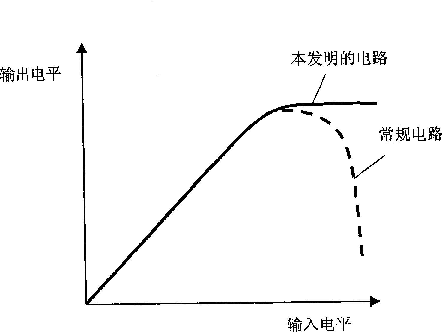
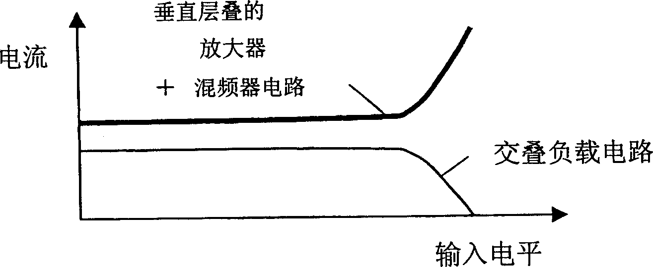
[0032] refer to Figure 2A and 2B describe figure 1 The characteristics of the signal receiving front-end circuit in . Figure 2A The relationship between IF output level and input level is shown. Figure 2B The relationship between the current consumed by the mixer circuit an...

no. 2 example

[0038] image 3 is a block diagram of a signal receiving front-end circuit according to a second embodiment of the present invention. image 3 The signal receiving front-end circuit of the first embodiment includes the signal receiving front-end circuit ( figure 1 ) of the same components. It should be noted that the average level detection circuit 10 is connected to the input terminal of the mixer circuit, but not connected to the output terminal of the load circuit 8 . The average level detection circuit 10 detects the average AC amplitude level of the input signal to the mixer circuit. Components other than the average level detection circuit 10 operate in a similar manner to the corresponding components of the signal receiving front-end circuit of the first embodiment. The signal receiving front-end circuit of the second embodiment has a function similar to that of the signal receiving front-end circuit of the first embodiment.

no. 3 example

[0040] Figure 4 is a block diagram of a signal receiving front-end circuit according to a third embodiment of the present invention. Figure 4 Two received signals are processed by the signal receiving front-end circuit of the signal receiving front-end circuit which is a modification of the signal receiving front-end circuit of the first embodiment. The signal receiving front-end circuit includes constant current sources 1a and 1b of the overlapping current mirror circuit, upper transistors 2a and 2b of the Gilbert mixer circuit, lower transistors 3a and 3b of the Gilbert mixer circuit, Gilbert Transmitter inductors 4a and 4b of the mixer circuit, signal input terminals 5a and 5b, local signal input terminals 6a and 6b, secondary transistor 7 of the overlapping current mirror circuit, load circuit 8, IF output terminal 9, average level Detection circuit 10, filter circuit 11, reference comparison circuit 12, limiter circuits 13a and 13b, and bias circuits 14a and 14b.

[0...


PUM


Abstract

An average level detection circuit (10) outputs a level of an input signal of a baseband output signal or a mixer circuit. A smoothing circuit (11) removes an AC component from an output signal of the average level detection circuit (10). A reference comparison circuit (12) outputs a level suppression signal when an output signal of the smoothing circuit (11) exceeds a predetermined reference voltage. When the reference comparison circuit (12) outputs the level suppression signal, the limiter circuit (13) controls the bias circuit (14) to suppress a bias current of the mixer circuit. As a result, it is possible to obtain a low-current-consumption signal reception front-end circuit in which an IF output level is not significantly lowered under an unexpectedly strong input condition, and a signal reception circuit in which an error does not occur in signal reception level detection.

Description

technical field [0001] The present invention relates to a signal receiving circuit used in mobile communication equipment and the like and a signal receiving front end circuit included in the signal receiving circuit. Background technique [0002] Recently, in order to reduce the size of mobile communication devices, research is being conducted on the structure of wireless circuits using semiconductor integrated circuits. Furthermore, in order to reduce the power consumption of wireless circuits, techniques for sharing current among multiple circuit blocks and techniques for extending the dynamic range at low voltages have also been studied. [0003] Figure 11 is a diagram of a circuit disclosed in Japanese Patent Laid-Open No. H5-37245, in which a current is shared among a plurality of circuit blocks. exist Figure 11 In the circuit of , the circuit 802 is connected to the power source 803 through the power line 810 and the resistive element 814 . Also, the power supply ...

Claims


Application Information

Patent Timeline
Patent Type & Authority Applications(China)
IPC IPC(8): H03D7/00
CPCH03D7/1458H03D7/1491H03D2200/0043H03D2200/0025H04B1/1607H03D7/1433H03D2200/0033
Inventor 石田薰小森浩
Owner PANASONIC CORP
Why Eureka
Try Eureka