Operating tunnel gas monitoring device and system based on passive laser methane sensor

A technology of methane sensor and monitoring device, which is applied to measurement devices, instruments, scientific instruments, etc., can solve the problems of communication interruption failure of the upper computer, inconvenient maintenance and maintenance, and high failure probability, so as to achieve convenient maintenance, improve safety and communication capabilities. , the effect of long life

Inactive Publication Date: 2019-08-13
四川矿隧环境检测有限公司
View PDF9 Cites 2 Cited by
  • Summary
  • Abstract
  • Description
  • Claims
  • Application Information

AI Technical Summary

Problems solved by technology

[0004] 1. The conventional mining laser methane sensor is installed 20-30cm below the top (possible laminar flow space). The sensor itself needs power supply (voltage is generally 5V). The intrinsically safe power supply for the sensor is designed with several levels of protection measures, but In extreme cases, it is still possible to generate sparks and cause gas combustion or explosion (such as strong current in series, lightning strikes, etc. to break down electrical components)
[0005] 2. The catenary voltage level on the top of the high-speed rail is 25KV, which will generate a strong electromagnetic field, and the laser methane sensor is installed 20-30cm below the top, and itself and its 485 communication line will be subject to strong electromagnetic interference, which will inevitably cause communication with the host computer. interrupt fault
[0006] 3. The conventional mining laser methane sensor integrates detection components, signal processing circuit, power supply circuit, signal output circuit, display circuit, alarm signal and other components, and has a high failure rate. Install it on the top of the tunnel and repair it in case of failure , maintenance is extremely inconvenient
The existing coal mine monitoring system does not have this linkage function

Method used


Image

  • Operating tunnel gas monitoring device and system based on passive laser methane sensor
  • Operating tunnel gas monitoring device and system based on passive laser methane sensor
  • Operating tunnel gas monitoring device and system based on passive laser methane sensor

Examples


Embodiment Construction

[0034] In order to understand the above-mentioned purpose, features and advantages of the present invention more clearly, the present invention will be further described in detail below in conjunction with the accompanying drawings and specific embodiments. It should be noted that, under the condition of not conflicting with each other, the embodiments of the present application and the features in the embodiments can be combined with each other.

[0035] In the following description, many specific details are set forth in order to fully understand the present invention. However, the present invention can also be implemented in other ways different from the scope of this description. Therefore, the protection scope of the present invention is not limited by the following disclosure. limitations of specific examples.

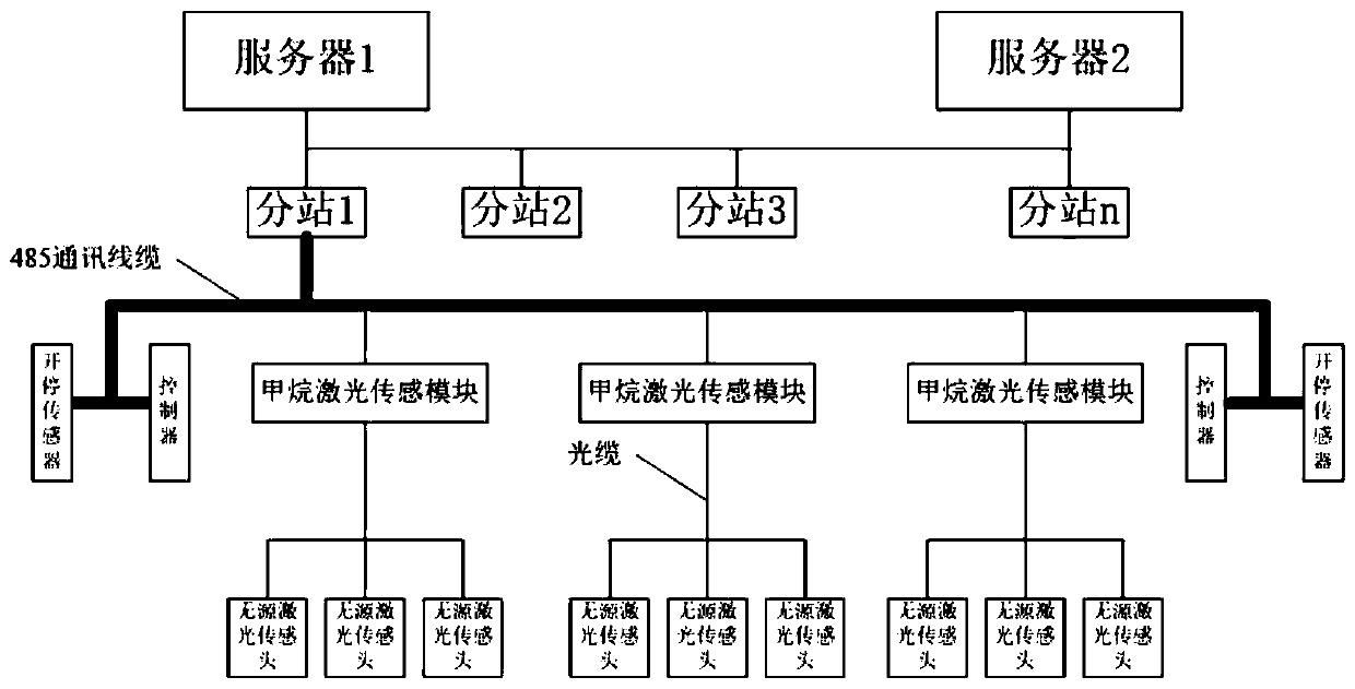
[0036] Please refer to figure 1 , this application provides a gas monitoring device for operating tunnels based on passive laser methane sensors, figure 1 (Sch...


PUM


Abstract

The invention discloses an operating tunnel gas monitoring device and system based on a passive laser methane sensor. The device comprises a fiber laser methane sensor device, a signal processing circuit and a power supply circuit, wherein the fiber laser methane sensor device is used for detecting methane content information, and transmitting the detected methane content information to the signalprocessing circuit; the signal processing circuit processes the detected methane content information; the power supply circuit is used to supply power to the fiber laser methane sensor device and thesignal processing circuit; the fiber laser methane sensor device comprises a laser generator and a methane sensor, and the methane sensor is installed in a methane gathering area preset at the top portion in the tunnel; the laser generator and the methane sensor are connected through the optical fiber; and the laser generator, the signal processing circuit and the power supply circuit are installed a non-methane gathering area outside or in the tunnel. The operating tunnel gas monitoring device based on the passive laser methane sensor improves the safety of the tunnel gas monitoring system and enhances its communication anti-interference.

Description

technical field [0001] The invention relates to the field of tunnel safety monitoring, in particular to an operating tunnel gas monitoring device and system based on a passive laser methane sensor. Background technique [0002] The density of methane is lower than that of air, and the methane that penetrates into the inner space of the tunnel through the tunnel lining will migrate to the head space of the tunnel; generally, the entrance and exit of railway tunnels have a certain height difference, which can form a certain natural wind pressure, and the tunnel is generally There is a natural wind flow, but the wind direction and wind speed change at any time with the temperature, humidity and other climate conditions at both ends of the tunnel (the situation is more complicated when there is a ventilation shaft in the middle), which is completely uncontrollable, and the wind flow may be static in extreme cases; The piston ventilation is formed when the train is passing, and t...

Claims


Application Information

Patent Timeline
Patent Type & Authority Applications(China)
IPC IPC(8): G01N21/17
CPCG01N21/17
Inventor 曾志斌曾卓敬洪武奂炯睿薛斌许洋健
Owner 四川矿隧环境检测有限公司
Why Eureka
Try Eureka