Stall self-locking mechanism for household wind driven generator transmission shaft in field of new energy

A wind turbine, new energy technology, applied in the direction of liquid resistance brakes, renewable energy integration, mechanical equipment, etc., can solve the problems of wind power generation equipment damage, affecting the safe operation of equipment, damage to generator sets, etc., to avoid power overload. problems, prevent excessive internal temperature, and ensure the effect of equipment safety

Active Publication Date: 2020-08-18
湖南驰兴工程建设有限公司
View PDF10 Cites 11 Cited by
  • Summary
  • Abstract
  • Description
  • Claims
  • Application Information

AI Technical Summary

Problems solved by technology

Due to the limited installed power of the generator set, there is a certain limit on the rotation speed of the transmission shaft and the fan blade. When the fan blade and the transmission shaft rotate too fast, the power of the generator set will be overloaded, which will not only cause energy waste It will directly lead to the damage of the generator set and bring certain property losses.
At the same time, the overload of the generator set will often lead to excessive internal temperature, and even cause the generator set to burn, causing irreversible damage to the entire wind power generation equipment, resulting in complete damage to the equipment, and seriously affecting the safe operation of the equipment.
In addition, the combustion of the generator set may ignite other objects, because there is a great potential safety hazard for household power generation equipment
[0004] In order to solve the above problems, the inventor proposed a stall self-locking mechanism for the transmission shaft of household wind power generators in the field of new energy, which has the advantage of stall self-locking and effectively avoids the problems caused by the overspeed of the generator set

Method used


Image

  • Stall self-locking mechanism for household wind driven generator transmission shaft in field of new energy
  • Stall self-locking mechanism for household wind driven generator transmission shaft in field of new energy
  • Stall self-locking mechanism for household wind driven generator transmission shaft in field of new energy

Examples


Embodiment Construction

[0024] The following will clearly and completely describe the technical solutions in the embodiments of the present invention with reference to the accompanying drawings in the embodiments of the present invention. Obviously, the described embodiments are only some, not all, embodiments of the present invention. Based on the embodiments of the present invention, all other embodiments obtained by persons of ordinary skill in the art without making creative efforts belong to the protection scope of the present invention.

[0025] see Figure 1-6 :

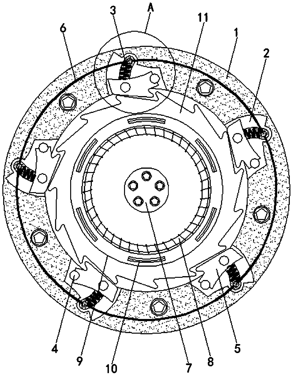
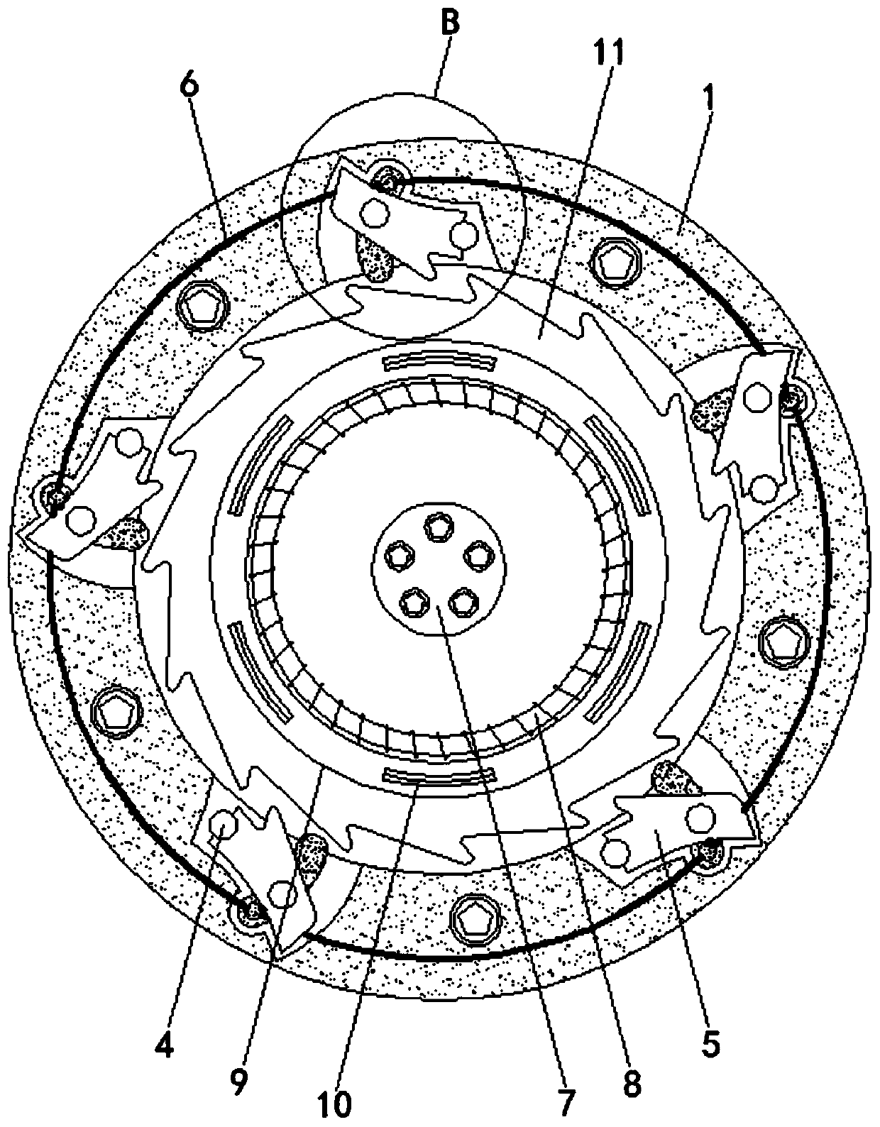
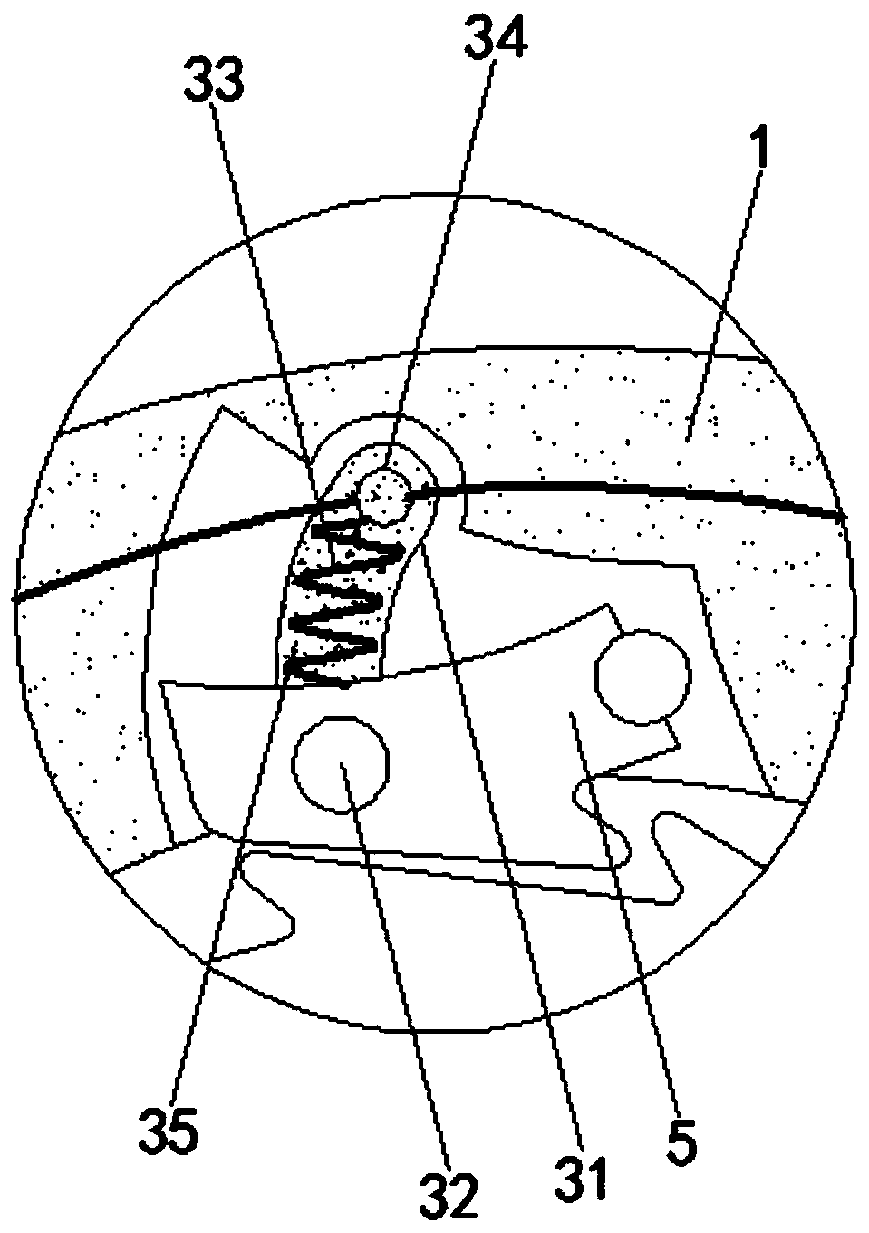
[0026] The stall self-locking mechanism for the transmission shaft of household wind power generators in the new energy field includes a mounting base 1, a movable chamber 2, a self-locking mechanism 3, a hinge column 4, a self-locking block 5, a wire 6, a main wheel 7, a coil 8, Axle 9, conductor 10, self-locking disk 11, encapsulation shell 31, movable column 32, return spring 33, conductive column 34, current variant 35.

[0027...


PUM


Abstract

The invention relates to the technical field of new energy, in particular to a stall self-locking mechanism for a household wind driven generator transmission shaft in the field of new energy. The stall self-locking mechanism comprises a mounting seat, movable cavities are formed inside the mounting seat, self-locking mechanism bodies are arranged inside the movable cavities, hinge columns are movably connected inside the movable cavities, and self-locking blocks are movably connected to the outer sides of the hinge columns. According to the stall self-locking mechanism for the household winddriven generator transmission shaft in the field of the new energy, automatic locking can be achieved so as to stop rotating of a generator set when the rotating speed of the generator set exceeds therated rotating speed, so that the problem of equipment damage caused by power overload of the generator set is effectively solved, meanwhile, the situation that the internal temperature of the generator set is too high or the generator set is burnt due to power overload is completely eradicated, the safety of wind power generation equipment is greatly protected, and the normal operation of the equipment is guaranteed. Meanwhile, various potential safety hazards possibly caused by power overload of the generator set are eliminated, and the requirements and use specifications of the nation forthe new energy technology are better met.

Description

technical field [0001] The invention relates to the field of new energy technology, in particular to a stall self-locking mechanism for a transmission shaft of a household wind power generator in the field of new energy. Background technique [0002] With the acceleration of environmental pollution and energy consumption, a series of problems brought about by traditional fossil energy have gradually been paid attention to by people. Because traditional fossil fuels produce a lot of pollutants when burned or used, and fossil energy has the disadvantage of being non-renewable, various clean new energy facilities have begun to occupy the energy market, among which solar energy and wind energy are the most widely used . [0003] As a new energy source, wind power generation has low construction cost and high power generation efficiency. Therefore, in addition to large-scale wind farms, various household wind power generation equipment is gradually being promoted. The main prin...

Claims


Application Information

Patent Timeline
Patent Type & Authority Applications(China)
IPC IPC(8): F16D63/00F16D59/00F16D57/00
CPCF16D57/002F16D59/00F16D63/00Y02B10/30
Inventor 赵群燕
Owner 湖南驰兴工程建设有限公司
Why Eureka
Try Eureka