Ceramic envelope device, lamp with such device

A technology of ceramic shells and components, used in discharge lamps, electrical components, gas discharge lamps, etc.

Inactive Publication Date: 2004-09-29
OSRAM SYLVANIA INC
View PDF10 Cites 1 Cited by
  • Summary
  • Abstract
  • Description
  • Claims
  • Application Information

AI Technical Summary

Problems solved by technology

As a result, separate metal feedthroughs are required

Method used


Image

  • Ceramic envelope device, lamp with such device
  • Ceramic envelope device, lamp with such device
  • Ceramic envelope device, lamp with such device

Examples


Embodiment Construction

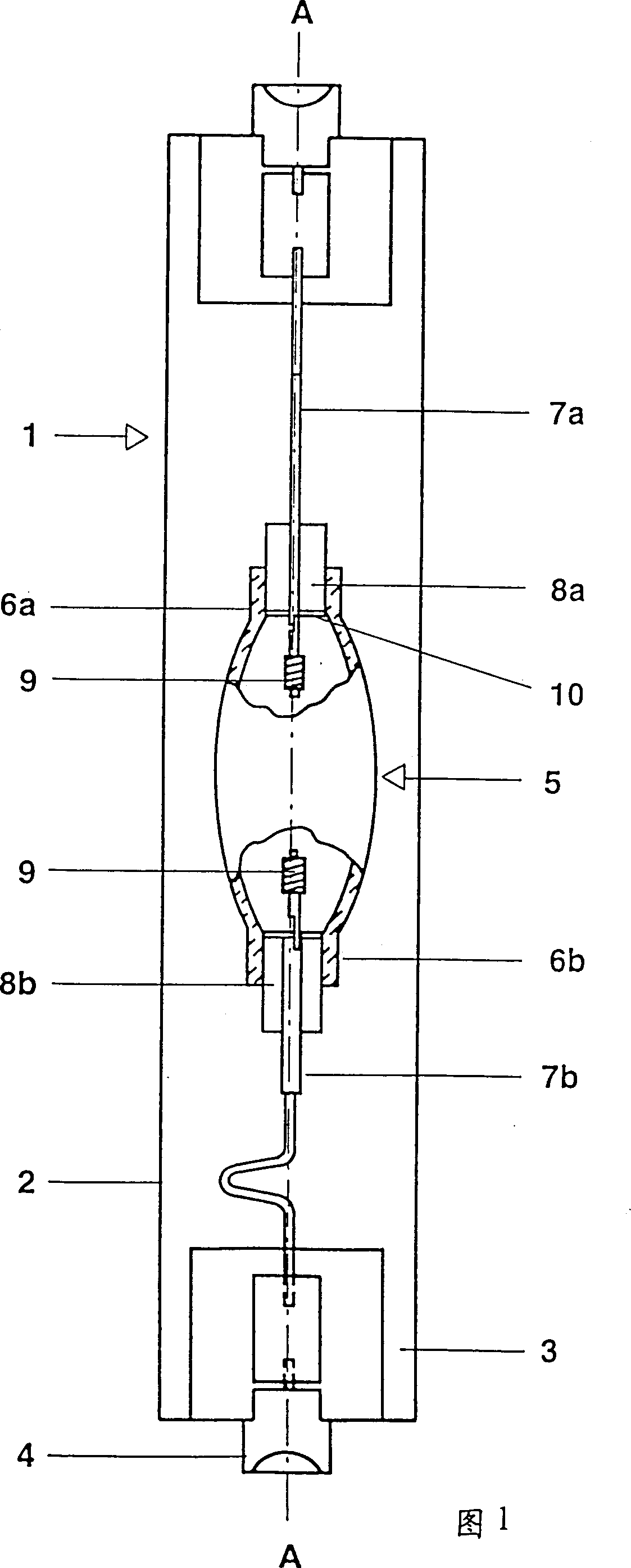
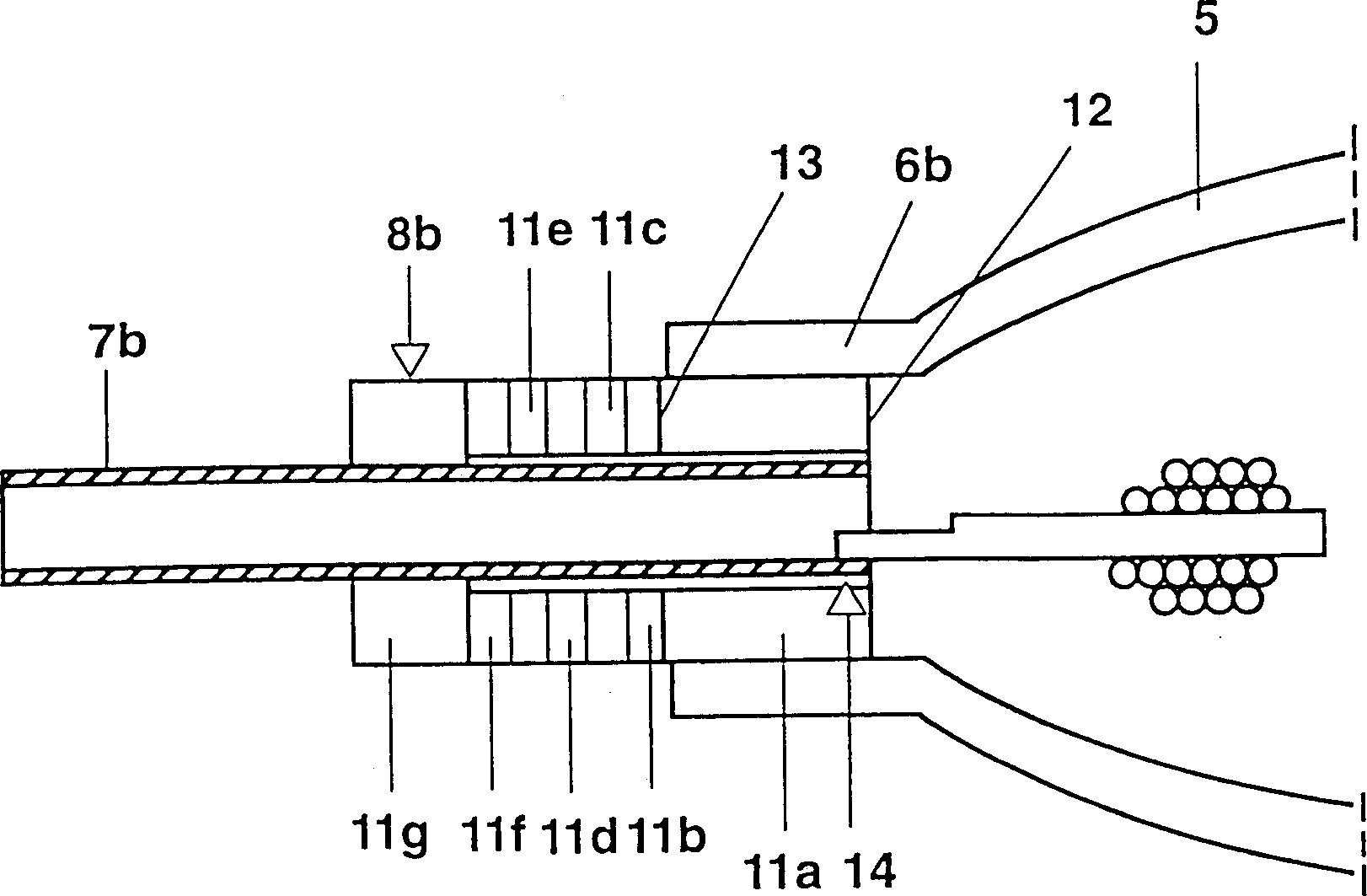
[0094] To illustrate, first refer to FIG. 1, which shows a highly schematic view of a metal halide discharge lamp 1 with a rated power of 150W. This lamp has a substantially cylindrical shell 2 made of quartz glass, which is compressed and sealed at its end 3, and has a base 4. The ceramic shell assembly 5 functions as a discharge vessel or arc tube, and it is enclosed in the shell 2. The ceramic shell assembly 5 is made of alumina, which determines the central longitudinal axis A and has two ends. For example, it is made into a cylindrical tube (not shown) or it protrudes outward at the center as shown in the figure. It forms cylindrical ends 6a and 6b at both ends. The two current through wires 7a, 7b are matched with ceramic (cermet) end plugs 8a, 8b, and the end plugs 8a, 8b are located at the ends 6a and 6b.

[0095] The first current through wire 7a is a molybdenum rod, which is sintered directly into the first end plug 8a at the first end 6a. The end plug is a single-piece ...


PUM


Abstract

This invention involves a new type of feedthrough-plug member for metal halide HID lamp using PCA envelopes. The construction of the lamp housing consists of a PCA envelope and specially designed axially graded alumina-metal cermet multi-layers to eliminate cracking in cermet or PCA due to thermal stresses arising from thermal expansion mismatch. The fills are metal halides such as Na-Sc-I, rare earth halides, Hg, Sn, and inert gases. The PCA vessel and directly sealed cermet-feedthrough assemblies allow the metal halide lamps to operate at high wall temperatures with better lumen output, color temperature, and CRI.

Description

Technical field [0001] The present invention relates to a ceramic shell assembly, to a lamp with such a device, and more preferably to a metal halide lamp with a polycrystalline alumina shell, the end of which is closed by a ceramic end plug. More precisely, the present invention is directed to a device having at least one cermet end plug, the cermet end plug has a plurality of parts or a plurality of loops or layers whose thermal expansion coefficient gradually changes. In addition, it relates to the cermet end plug itself and the method of manufacturing the cermet end plug. Background technique [0002] It is intended that metal halide high intensity discharge lamps (HID) operate at high wall temperatures in order to improve their efficiency, change the color temperature, and / or increase the color rendering index of the light source. Generally, metal halide lamps include a filling of one or more metals such as sodium (Na) halides (particularly iodides and bromides). Na is often...

Claims


Application Information

Patent Timeline
IPC IPC(8): H01J61/30H01J9/32H01J61/36
CPCH01J61/366H01J9/323
Inventor S·朱恩斯特G·C·维R·蒂波德奥J·瑟维里安
Owner OSRAM SYLVANIA INC
Why Eureka
Try Eureka