Plasma display panel

A technology for display panels and phosphors, which can be applied to alternating current plasma display panels, gas discharge electrodes, solid cathode components, etc., and can solve problems such as the reduction of color purity

Inactive Publication Date: 2004-10-13
PANASONIC CORP
View PDF1 Cites 0 Cited by
  • Summary
  • Abstract
  • Description
  • Claims
  • Application Information

AI Technical Summary

Problems solved by technology

[0012] The above-mentioned problems, that is, reduction in color purity and halation, are fundamental problems in conventional plasma display panels regardless of the number of discharge cells or the display light from the discharge cells

Method used


Image

  • Plasma display panel
  • Plasma display panel
  • Plasma display panel

Examples


Embodiment Construction

[0023] Hereinafter, an embodiment of the plasma display panel of the present invention will be described in detail with reference to the accompanying drawings.

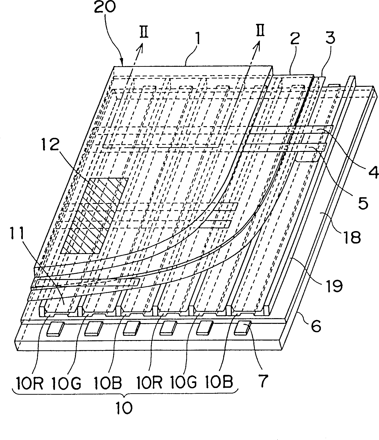
[0024] figure 1 is an enlarged perspective view of a portion of a plasma display panel of the present invention, generally indicated by reference numeral 20 . As shown in the figure, the structure of the display panel 20 of the present invention is the same as Figure 5 The structure of the plasma display panel 20' shown in is basically the same. Therefore, the description of the structure of the plasma display panel 20 is omitted, and in figure 1 and Figure 5 The same parts and accessories having the same function in have the same reference number.

[0025] The difference between the plasma display panels 20 and 20' lies in the materials of the base glass layer and the ribs. Specifically, although the material of the base glass layer 8 and the ribs 9 of the plasma display panel 20' in the prior art has a white ...


PUM

PropertyMeasurementUnit
Thicknessaaaaaaaaaa
Thicknessaaaaaaaaaa

Abstract

A plasma display panel has spaced apart and parallel first and second substrates substrate. A base glass layer is provided on one surface of the second substrate confronting to the first substrate. A plurality of spaced apart parallel ribs are positioned on the base glass layer and between first and second substrates. Each rib defines a channel with another neighboring rib. A plurality of phosphor capable of emitting light are provided, each of which being positioned in the channel. In particular, the base glass layer and / or ribs are made of material substantially impermeable to light.

Description

technical field [0001] The present invention relates to a display element and a plasma display panel especially for image display of televisions and computers. Background technique [0002] exist Figure 5 A conventional AC plasma display panel is described in . like Figure 5 As shown, a plurality of scan electrodes 4 and sustain electrodes 5 are formed on a first insulating substrate 1 parallel to each other. Scan electrodes 4 and sustain electrodes 5 are covered by a dielectric layer 2 and a protective layer 3 . A plurality of data electrodes 7 parallel to each other and perpendicular to the scan electrodes 4 and the sustain electrodes 5 are formed on the second insulating substrate 6 facing the first insulating substrate 1 . The data electrodes 7 are covered by a base glass layer 8 made of white material. Formed on the base glass layer 8 are a plurality of ribs 9 also made of white material. Ribs 9 are arranged such that each rib cooperates with an adjacent rib to de...

Claims


Application Information

Patent Timeline
IPC IPC(8): H01J11/12H01J11/22H01J11/24H01J11/26H01J11/34H01J11/36H01J11/38H01J11/42H01J11/44H01J17/04
CPCH01J11/44H01J2211/444H01J2211/38H01J11/12H01J2211/366H01J11/34H01J11/36
Inventor 平尾和则青砥宏治田原宣仁
Owner PANASONIC CORP
Why Eureka
Try Eureka