Optical disk with oscillating convex region and groove
An optical disc and optical disc recording technology, applied in the direction of groove/land recording, optical record carrier, disc record carrier, etc., can solve the problems of increased redundancy, time-consuming, and inability to record continuous data, etc.
- Summary
- Abstract
- Description
- Claims
- Application Information
AI Technical Summary
Problems solved by technology
Method used
Image

Examples
Embodiment 1
[0040] Fig. 4 is a schematic diagram of an optical disc according to a first embodiment of the present invention.
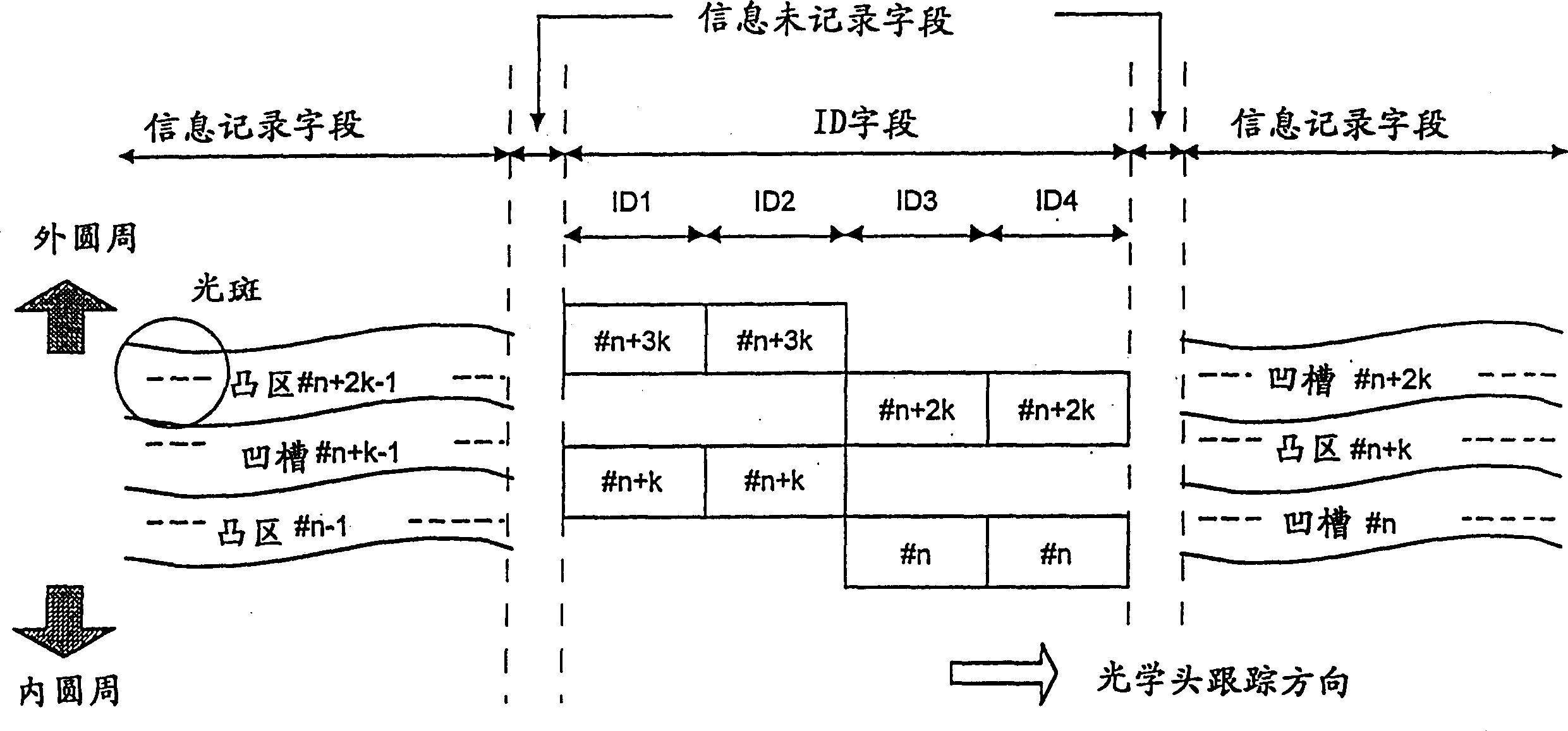
[0041] As shown in Figure 4, the guide track of the optical disc is arranged so that the optical head can perform the same tracking when recording and reproducing information, and the optical disc is designed so that the groove (solid line) and the land (dotted line) are interchanged every revolution. once. There are a large number of sectors in one rotation, and the sector is composed of an ID field, an information recording field and an information non-recording field. The guide tracks shown are helical, but they could also be concentric or reverse helical. The number of sectors per revolution is also arbitrary.
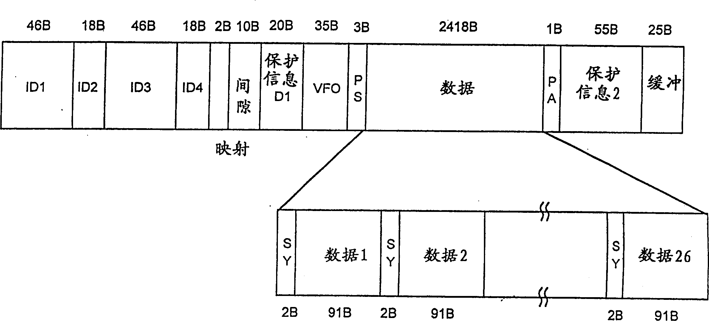
[0042] figure 1 A portion where grooves and lands are interchanged on the optical disk of the first embodiment of the present invention is shown. The ID field consists of 4 parts, ID1, ID2, ID3, ID4, each of which includes address information, an...
Embodiment 2
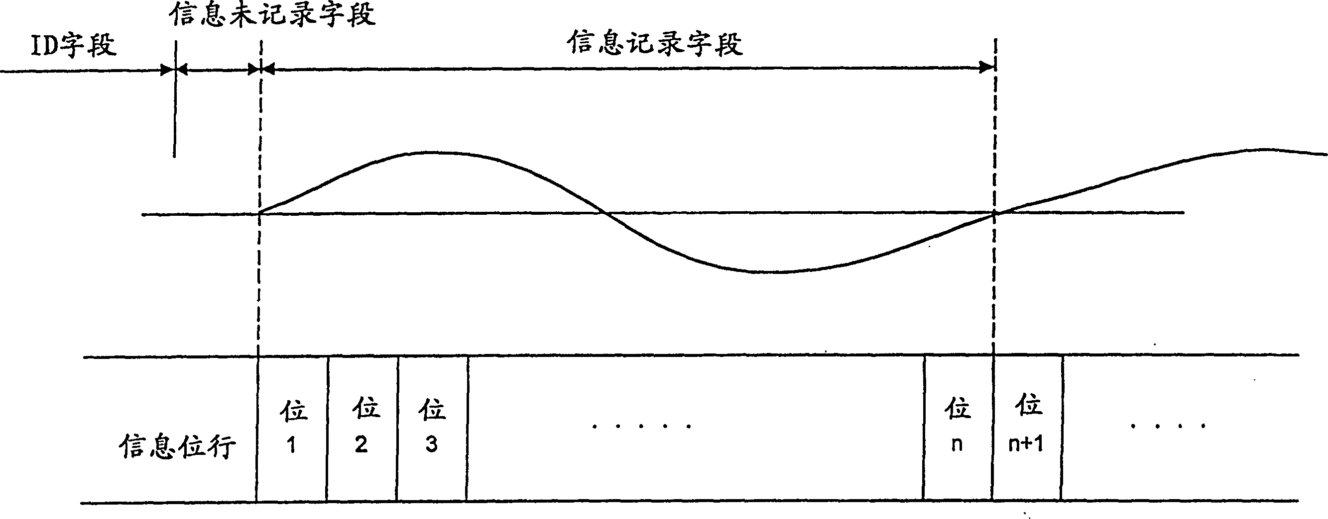
[0068] FIG. 6(a) shows an address field of an optical disc in an L / G (land and groove information recording and reproduction) system on the optical disc of the second embodiment of the present invention. On the optical disc in FIG. 6( a ), the address information of the ID field consists of two set bits, which are offset by 1 / 2 of the track pitch relative to the inner circumference side or the outer circumference side. The width of the convex and concave signals is substantially equal to the width of the grooves and lands of the information recording field. The grooves and lands change at each turn of the track. The ID field is composed of two parts, IDa and IDb, each containing address information, and deviated from the guide track to the inner circumferential side or the outer circumferential side by a distance of about 1 / 2 of the track pitch. That is, one address is shared by adjacent grooves and lands. The guide track (information recording field) wobbles in a direction ...
Embodiment 3
[0079] FIG. 8(a) shows an address field of an optical disc in an L / G (land and groove recording and reproduction) system on an optical disc in a third embodiment of the present invention. In the optical disc of FIG. 8( a ), the address information of the ID field is independently provided in the land and the groove, and is located in the middle of the land and the groove. To suppress interference from adjacent tracks, the pit width of the land and groove signals of the ID field is smaller than the width of the grooves or lands.
[0080] FIG. 8(b) explains the phase deviation of the wobble at the transition point of the groove and the land on each track of the optical disk of the third embodiment of the present invention. The wobble has an integer multiple of periods per sector, and the track has an integer multiple of sectors per revolution. Therefore, the wobble phase is continuous during one revolution of the disc, but due to manufacturing effects such as rotational fluctua...
PUM
 Abstract
Description
Claims
Application Information
 - R&D
- Intellectual Property
- Life Sciences
- Materials
- Tech Scout
- Unparalleled Data Quality
- Higher Quality Content
- 60% Fewer Hallucinations
Browse by: Latest US Patents, China's latest patents, Technical Efficacy Thesaurus, Application Domain, Technology Topic, Popular Technical Reports.
© 2025 PatSnap. All rights reserved.Legal|Privacy policy|Modern Slavery Act Transparency Statement|Sitemap|About US| Contact US: help@patsnap.com