Wave motion-reducing floating structure

A floating structure and wave technology, applied in the direction of reducing the motion of ships by attenuating waves, equipment to reduce the motion of ships, floating buildings, etc., can solve problems such as large translational motions

Inactive Publication Date: 2005-03-23
MITSUBISHI HEAVY IND LTD
View PDF2 Cites 0 Cited by
  • Summary
  • Abstract
  • Description
  • Claims
  • Application Information

AI Technical Summary

Problems solved by technology

[0007] Also, there are cases where translational m...

Method used


Image

  • Wave motion-reducing floating structure
  • Wave motion-reducing floating structure
  • Wave motion-reducing floating structure

Examples


Embodiment Construction

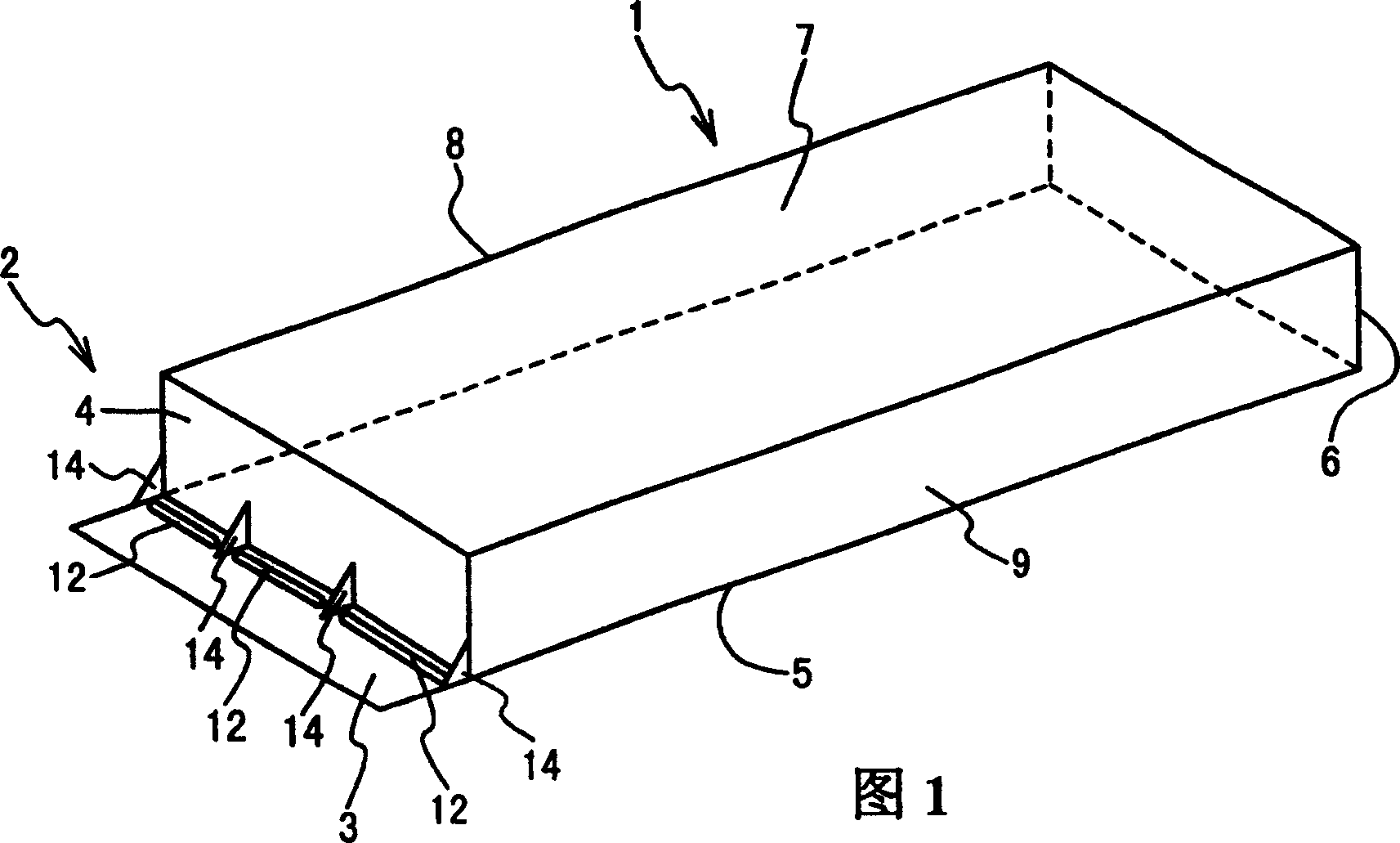
[0049] Hereinafter, the floating structure for reducing motion generated by waves of the present invention will be described in detail with reference to the accompanying drawings.

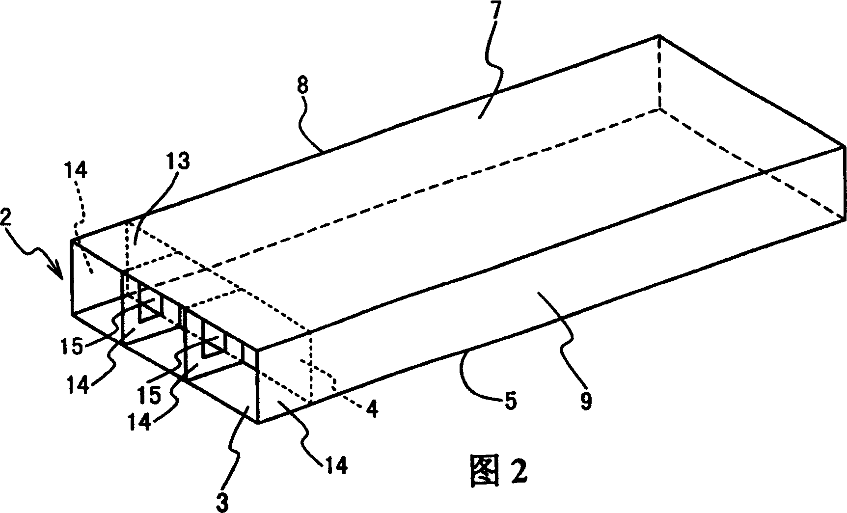
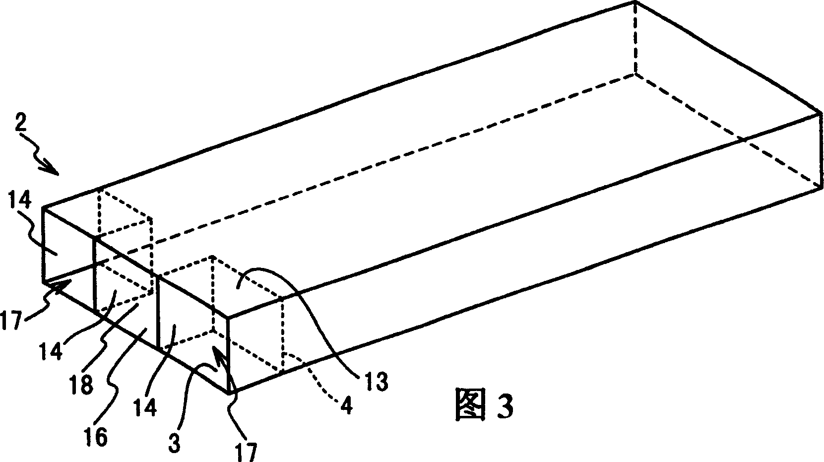
[0050] Figure 1 shows a floating structure with reduced wave-generated motion according to a first embodiment of the invention. Referring to FIG. 1 , a floating structure for reducing wave-generated motion in a first embodiment includes a main hull structure 1 in the shape of a rectangular parallelepiped box and a wave attenuator disposed on the wave-intruding side of the main hull structure 1 . Structure 2. The main hull structure 1 is used alone in the installed state of the L-shaped wave damping structure 2 or as a unit floating structure of a floating structure of a chain structure. The floating structure of the chain structure can be used as a leisure center at sea and as a resupply base in the event of a shipwreck.

[0051] The main hull structure 1 includes lower horizontal plates 5 and up...


PUM


Abstract

A motion reduced floating structure includes a main hull structure and a wave damping structure connected with the main hull structure. The wave damping structure may include a back board, a lower horizontal board and vertical members. The back board is connected with the main hull structure, and the lower horizontal board is connected with a lower portion of the back board to extend in a horizontal direction and is under a seawater surface in case of mooring. The vertical members are connected with the lower horizontal board and the back board. A vertical direction hole is provided for the lower horizontal board.

Description

technical field [0001] The present invention relates to a floating structure for reducing motion generated by waves, the structure having an L-shaped wave damping structure for reducing motion. Background technique [0002] A floating structure is considered to be a structure that is effectively used in ships. In ships used to transport people and cargo, fuel cost reduction is preferable to preventing rotational and translational motion. For this reason, a hemispherical structure is used as the bow shape to reduce wave resistance. In floating structures moored at predetermined positions, it is important to prevent movement on the horizontal plane. Movements on a horizontal plane include, for example, translational movements along the horizontal direction, rotational movements around a horizontal axis, and drifting movements. [0003] A wave damping device for a floating structure is also disclosed in US Pat. No. 6,102,625, which is used to attenuate the motion component c...

Claims


Application Information

Patent Timeline
IPC IPC(8): B63B39/10B63B35/34B63B35/44B63B39/06E02B3/06
CPCB63B39/06B63B35/34E02B3/064B63B2039/067B63B35/44
Inventor 松浦正己太田真谷垣信吉平井隆弘沟上宗二
Owner MITSUBISHI HEAVY IND LTD
Why Eureka
Try Eureka