Portal imaging device

An imaging device and a technology for mounting devices, which are applied in medical science, X-ray/γ-ray/particle irradiation therapy, and instruments for radiological diagnosis, and can solve problems such as expensive and foldable mounting devices

Inactive Publication Date: 2005-04-13
ELEKTA AB
View PDF1 Cites 0 Cited by
  • Summary
  • Abstract
  • Description
  • Claims
  • Application Information

AI Technical Summary

Problems solved by technology

Therefore, collapsible mounts such as the ones described above are actually very difficult and expensive for engineers and not always as accurate as desired

Method used


Image

  • Portal imaging device
  • Portal imaging device
  • Portal imaging device

Examples


Embodiment Construction

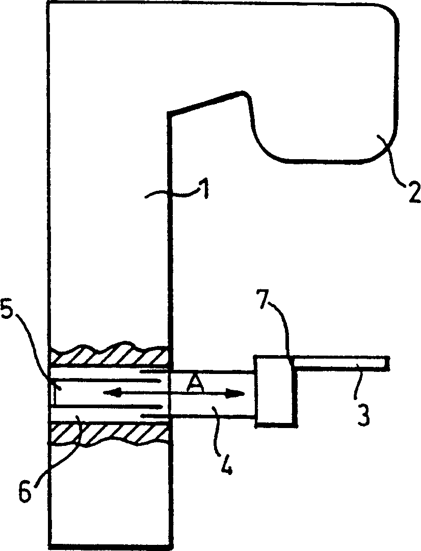
[0027] exist Figure 1 , the stand 1 of the radiotherapy device has a radiation head 2, radially opposite to the radiation head is an imaging device 3 connected with a telescopic arm, and the telescopic arm can be retracted into a cavity 6 in the stand 1 . The telescopic arm comprises two concentrically aligned tubes 4 , 5 , one of which can slide along the axis A inside the other. Imaging device 3 is pivotally mounted at point 7 at the distal end of tube 4 . The structure is shown in a fully extended position, but it will be appreciated that retraction of the tube 4 along the tube 5 into the cavity 6 and rotation of the imaging device 3 about the pivot 7 enables the assembly to be retracted and stowed into alignment with the radiotherapy device. Position the bench 1 flush with the surface.

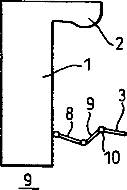
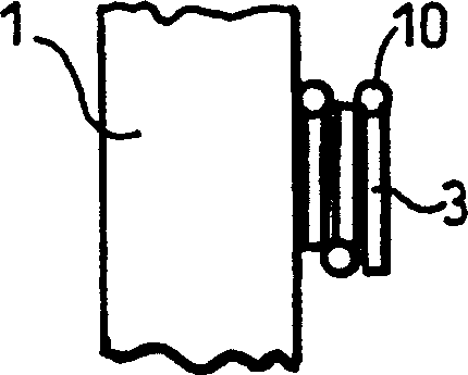
[0028] In FIG. 2 , the gantry 1 of the radiotherapy apparatus is pivotally connected to jointed arms 8 , 9 , which in turn are connected to an imaging device 3 via a pivot joint 10 . ...


PUM


Abstract

A surface mountable device for positioning an imaging device relative to a gantry of a radiation therapy device. The device includes: a mounting device for mounting the device on a stand surface; an extendable telescopic arm pivotally connected to the mounting device; and a holder for holding an imaging device, the A retainer is attached to the distal portion of the extendable telescopic arm. The device is mechanically simple and relatively cheap to manufacture. When assembled to a radiotherapy device, the device provides an accurate and lightweight device for positioning and stowing the imaging device.

Description

technical field [0001] The present invention relates to a radiotherapy device, especially a gantry (portal) imaging system, which includes a rotatable platform supported by a pedestal, a ray emitting head connected to the platform, and an imaging device. The imaging device is used for Visually represent the ray beam emitted by the emitter head and passing through the object to be treated. In particular, the invention relates to a device for mounting the imaging device on a gantry of a radiotherapy device. Background technique [0002] European Patent No. EP0541717 addresses a problem with gantry imaging devices that, in order for a light-weight box to cover a radiation field of suitable size, the structure of the detector housing would be very bulky, making it inconvenient for the patient during installation , and takes up space in the treatment room when not in use. Therefore, the practical use of this device has been very limited before. This patent discloses a device f...

Claims


Application Information

Patent Timeline
Patent Type & Authority Patents(China)
IPC IPC(8): A61B6/00A61N5/10
CPCA61B6/4429A61B6/4233
Inventor 罗伯特·S·库克克里斯托弗·J·弗赖尔威廉·R·哈伍德克里福德·W·珀金斯拉尔夫·P·斯特里默
Owner ELEKTA AB
Why Eureka
Try Eureka