Fare collection system and communication method therefor

A communication method and cost technology, applied in traffic control systems, road vehicle traffic control systems, traffic flow detection, etc., can solve the problems of high construction costs and high operating costs, and achieve relaxation of restrictions, accurate fee collection, and elimination of emissions. The effect of wave influence

Inactive Publication Date: 2005-04-27
HITACHI LTD
View PDF0 Cites 2 Cited by
  • Summary
  • Abstract
  • Description
  • Claims
  • Application Information

AI Technical Summary

Problems solved by technology

This will lead to high constru...

Method used


Image

  • Fare collection system and communication method therefor
  • Fare collection system and communication method therefor
  • Fare collection system and communication method therefor

Examples


Embodiment Construction

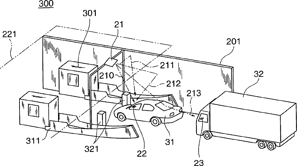
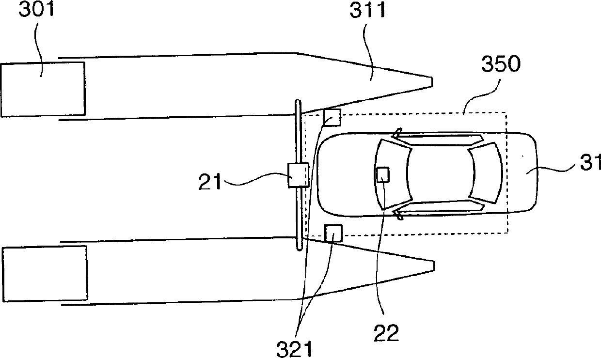
[0034] FIG. 3 is an embodiment of the level system proposed by the present invention. In the checkpoint 300, a roadside antenna 101 and a car sensor 320 are installed on the upper part or both sides of the checkpoint area, and other components are the same as those shown in FIG. 2 . Install multiple of these levels in the level area.

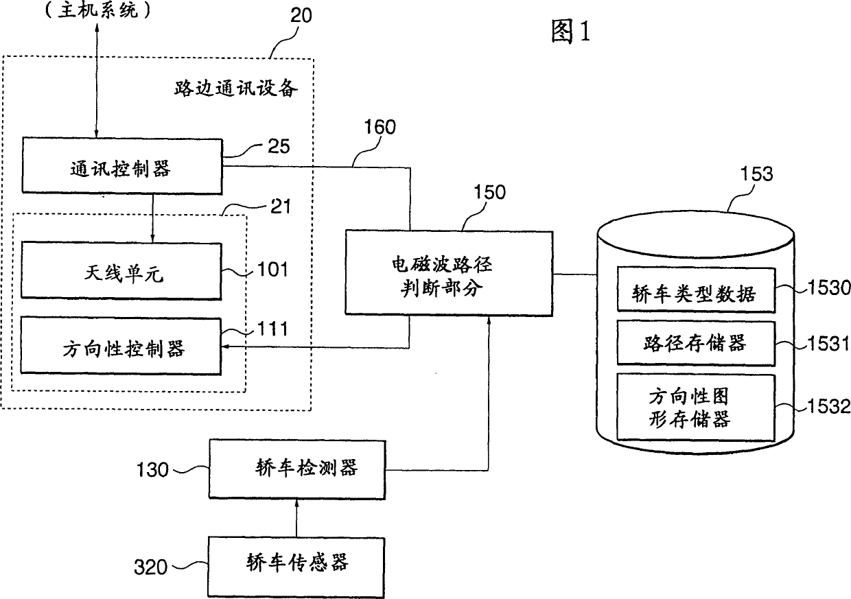
[0035] FIG. 1 shows the structure of a fee collection system according to an embodiment of the present invention. This fee collection system is provided with the following devices: a roadside communication antenna 21 composed of an antenna unit 101 and a directional controller 111 for controlling its directional pattern; The communication controller 25 of the necessary information about payment; One detects the automobile sensor 320 that automobile enters checkpoint; One judges the automobile data detector 130 of detected automobile position and outline; An electromagnetic wave path judging part 150, can be in antenna unit 101 and Select an el...


PUM


Abstract

An electronic toll collection system (ETCS) for use in a tollgate for charging a car without the need for the car to stop, in which communication failures or errors due to reflected waves from a structure or a passing car are prevented. A roadside communication antenna which communicates with a vehicle-mounted communication antenna for charging, and a car sensor which detects a car (cars) in an area wider than a designed communication area are installed at the tollgate. As an electromagnetic wave path judgment section obtains data on the profile and position of a car which has entered the tollgate, from a car data detector, it calculates electromagnetic wave paths of direct and reflected waves which connect the roadside communication antenna 21 and the vehicle-mounted antenna in each of the cars, and calculates the receiving electric field strength for each of the paths.

Description

technical field [0001] The invention relates to an electronic fee collection system based on the wireless communication of checkpoints, in particular to a communication method suitable for checkpoints in a wireless environment. Background technique [0002] An Electronic Toll Collection System (ETCS) is an electronic system that enables drivers to receive tickets or pay tolls without stopping at checkpoints on toll roads, such as highways. [0003] Figures 2A and 2B show a schematic diagram of a level using an ETCS. Fig. 2A is a perspective view, and Fig. 2B is a top view. The checkpoint 300 is separated from the adjacent passage area by a safety island 311 . A roadside communication antenna 21 is installed on the checkpoint 300 . When the car 31 with the vehicle-mounted communication antenna enters the designed communication area 350, the information required for payment is exchanged through wireless signals between the roadside communication antenna 21 and the vehicle-m...

Claims


Application Information

Patent Timeline
IPC IPC(8): G07B15/00G08G1/015G08G1/017G08G1/04G08G1/065
CPCG08G1/065G07B15/063G08G1/017G07B15/00
Inventor 佐藤义人加藤学
Owner HITACHI LTD
Why Eureka
Try Eureka