
Rolling mill oil film bearing conic sleeve

A technology of bearings and taper sleeves, which is applied in the direction of metal rolling stands, metal rolling mill stands, metal rolling, etc., can solve the problem of insufficient shape at both ends of bearing taper sleeves, which affects the service life of bearing taper sleeves, and Problems such as sleeve contact, to achieve the effect of easy assembly and advancement, improved service life, and uniform contact stress

Inactive Publication Date: 2005-05-25
太原重型机械学院
View PDF0 Cites 0 Cited by
  • Summary
  • Abstract
  • Description
  • Claims
  • Application Information

AI Technical Summary

Problems solved by technology

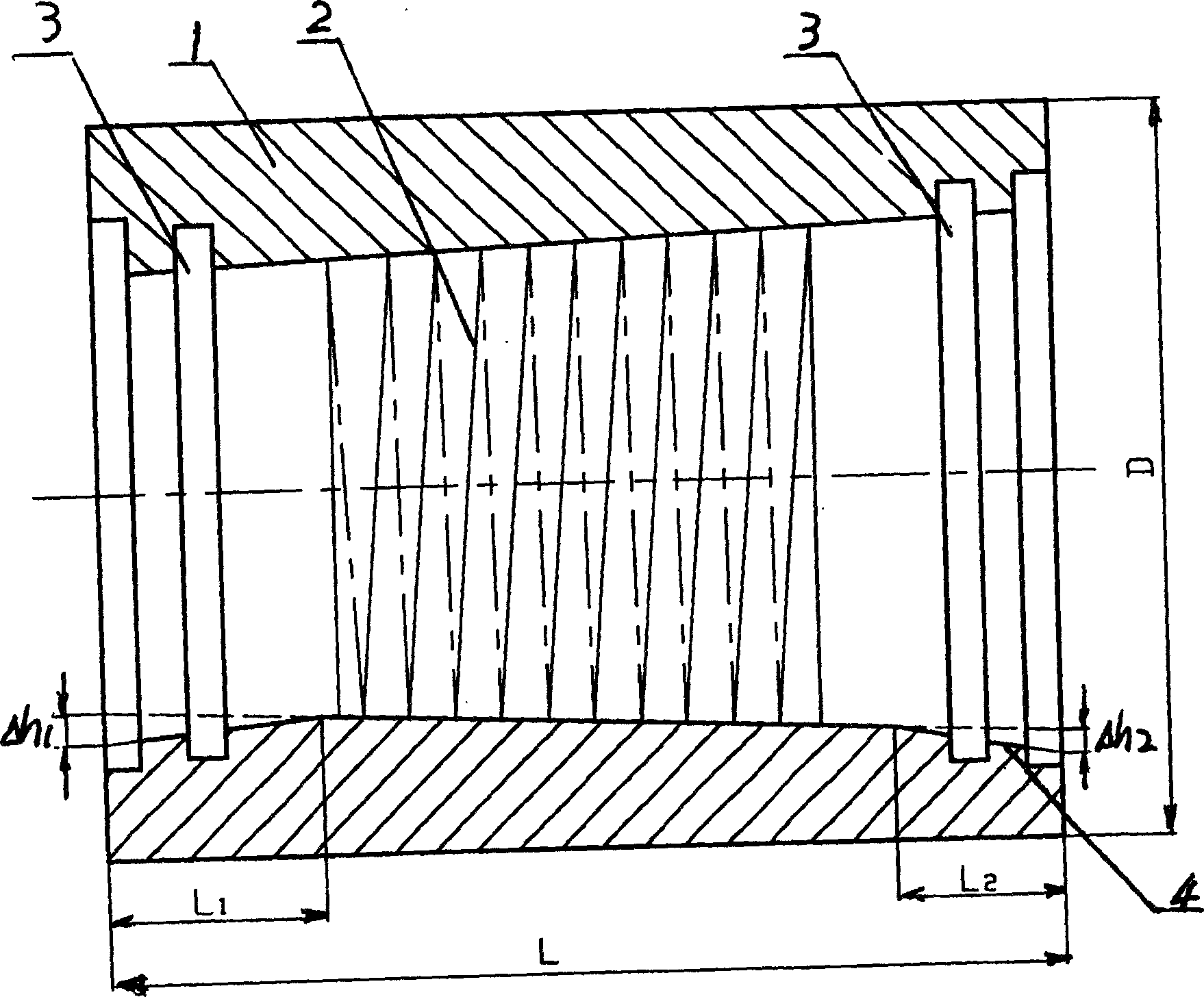
However, the disadvantage of this assembly method is that in the process of forming the bearing taper sleeve under high pressure, because the inner hole of the bearing taper sleeve has a certain taper, the wall thickness of the bearing taper sleeve along the axial direction is different, so that the hydraulic pressure is mainly concentrated in the The middle area of ​​the bearing tapered sleeve, and the two ends of the bearing tapered sleeve have insufficient account shape, resulting in a large peak pressure. During the process of assembly and advancement, the tapered sleeve is prone to contact with the roll neck and cause wear. In this way, It will seriously affect the service life of the bearing taper sleeve

Method used


Image

  • Rolling mill oil film bearing conic sleeve
  • Rolling mill oil film bearing conic sleeve
  • Rolling mill oil film bearing conic sleeve

Examples


Embodiment

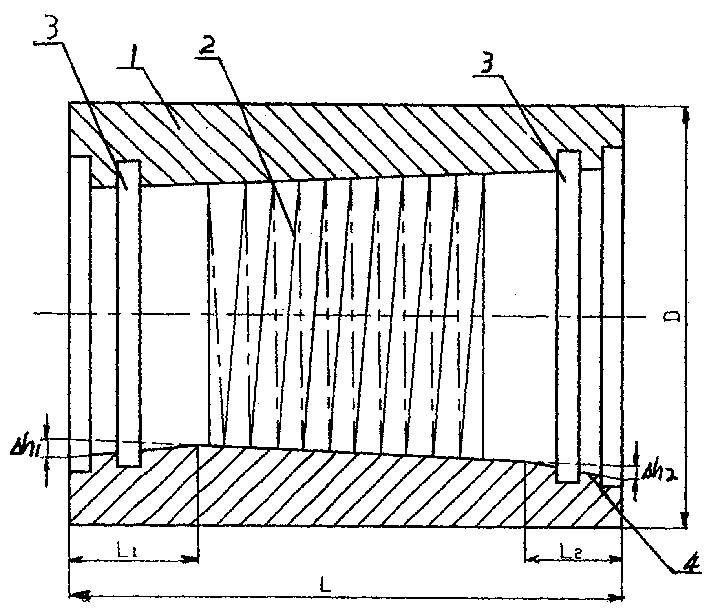
[0017] Example: such as figure 1 Shown in the middle and lower half, the two ends of the prior art rolling mill bearing taper sleeve are enlarged and made into a trumpet shape. Its specific dimensions are:

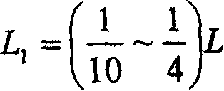
[0018] L 1 = ( 1 10 ~ 1 4 ) L L 2 = ( 1 10 ~ 1 4 ) L

[0019] Δ h 1 = ( 1 10000 ~ 1 600 ) D Δ h 2 = ( ...


PUM


Abstract

A rolling mill oil film bearing taper sleeve belongs to the technical field of steel rolling machinery, and is characterized in that the inner diameters of both ends of the rolling mill oil film bearing taper sleeve in the prior art are enlarged to form a tapered horn shape, see the size of the horn shape. ∴∴∴∴

Description

Technical field: [0001] The invention belongs to the technical field of steel rolling machinery, and in particular relates to a rolling mill oil film bearing taper sleeve. Background technique: [0002] At present, the connection between the oil film bearing taper sleeve of the rolling mill and the roll neck is an interference fit, that is, through the oil inlet hole at the end of the roll neck, high-pressure oil is injected into the middle of the bearing taper sleeve that has been set at the end of the roll neck. Make the bearing taper sleeve form an account shape, the inner hole becomes larger, and then push the bearing taper sleeve with the enlarged inner hole to the joint part of the roll neck, and then release the pressure so that the bearing taper sleeve and the roll neck are tightly connected together. However, the disadvantage of this assembly method is that in the process of forming the bearing taper sleeve under high pressure, because the inner hole of the bearing ...

Claims


Application Information

Patent Timeline
Patent Type & Authority Patents(China)
IPC IPC(8): B21B31/07
Inventor 黄庆学申光宪申福昌丁光正许将董宝力李玉贵
Owner 太原重型机械学院
Learn More